


7.7
Section 7
Cooling System
7
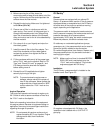
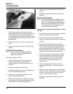
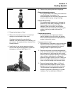
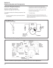
Figure 7-12. Adapter Installed onto the Tester.
2. Pressurize the tester to 15 psi.
3. Observe the indicated pressure. It should hold
steady and not decrease or leak down.
If leakage is detected, the cap should be
replaced. If the tester pressure is increased to 16
psi, or above, the cap should then ‘‘bleed off’’ this
excess pressure.
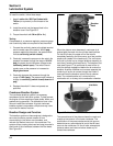
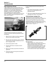
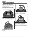
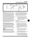
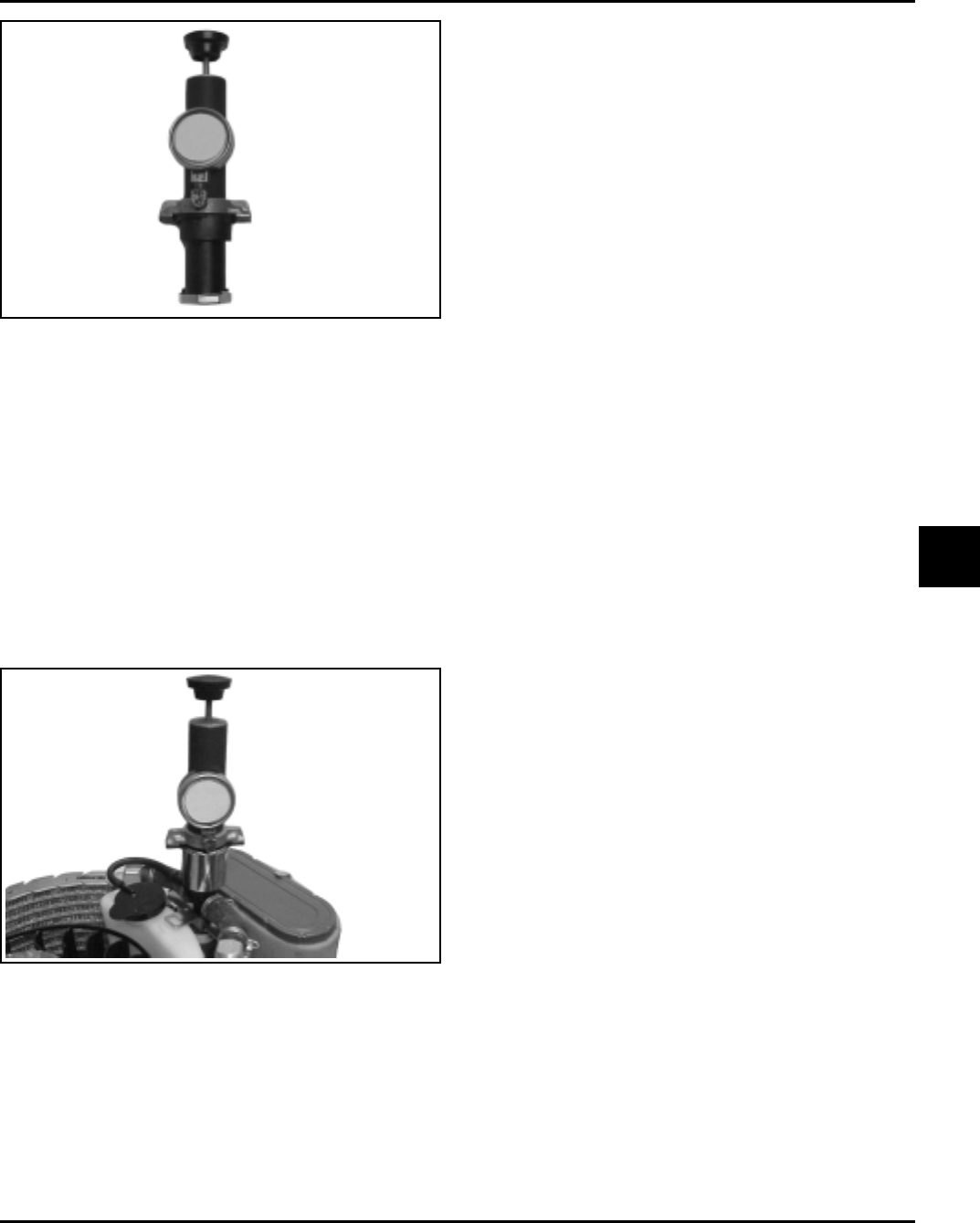
4. Install and lock the system adapter and tester
onto the neck of the cooling system. Pressurize
the tester to 14-15 psi. See Figure 7-13.
5. Observe the system pressure on the gauge.
Gauge holds steady pressure
If the gauge needle holds steady, there should be
no serious leaks in the system. It is
recommended that all connections be checked for
overall condition anyway, using a flashlight.
Pressure drops slowly
If the gauge needle drops slowly it indicates the
presence of a small leak or seepage. Check all
components and connections for signs of
leakage. Check the condition of the radiator
hoses. If they swell excessively while testing the
system, they may be weak and should be
replaced.
Pressure drops quickly
A steady drop or loss of pressure indicates
serious leakage is occurring within the system,
which must be located and corrected before the
engine is returned to service.
If a pressure loss is noted:
1. With pressure on the system, apply a soap/water
solution and check all joint connections, hoses,
and cooling system components for external
leakage. Repair or replace as required.
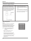
2. Remove the dipstick and check the appearance
of the oil in the crankcase. Another method would
be to remove an oil drain plug and drain a small
amount of oil for inspection. A milky or an opaque
color, similar to chocolate milk, indicates the
presence of engine coolant in the oil. Check for a
blown head gasket (step 3 below) or a possible
crack or internal leakage from the water jacket.
3. Remove the spark plugs. Apply 14-15 lbs. of
pressure and listen/inspect for internal coolant
leakage into the cylinder/combustion chambers.
This can denote a head gasket failure/leak. If
required, further test by performing a ‘‘Cylinder
Leakdown Test’’ as described in Section 3.
Figure 7-13. Adapter and Tester Installed.
15 psi
14-15
psi