


6.3
Section 6
Lubrication System
6
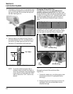
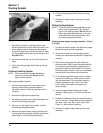
3. Before removing the oil filter, clean the
surrounding area to keep dirt and debris out of the
engine. Remove the old filter and wipe/clean the
surface where the filter mounts.
4. Reinstall the drain plug. Make sure it is tightened
to 13.6 N·m (10 ft. lb.).
5. Place a new oil filter in a shallow pan with the
open end up. Pour new oil, of the proper type, in
through the threaded center hole. Stop pouring
when the oil reaches the bottom of the threads.
Allow a minute or two for the oil to be absorbed by
the filter material.
6. Put a drop of oil on your fingertip and wipe it on
the rubber gasket.
7. Install the new oil filter to the filter adapter. Turn
the oil filter clockwise until the rubber gasket
contacts the surface, then tighten the filter an
additional 2/3-1 turn.
8. Fill the crankcase with new oil of the proper type,
to the ‘‘FULL’’ mark on the dipstick. Refer to ‘‘Oil
Type’’ and ‘‘Check Oil Level’’ on pages 6.1 and
6.2. Always check the level with the dipstick
before adding more oil.
9. Reinstall the oil fill cap/dipstick and tighten
securely by turning to the right.
NOTE: To prevent extensive engine wear or
damage, always maintain the proper oil
level in the crankcase. Never operate the
engine with the oil level below the ‘‘ADD’’
mark or above the ‘‘FULL’’ mark on the
dipstick.
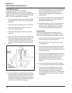
Angle of Operation
This engine will operate continuously at angles up to
20º. Check oil level to assure crankcase oil level is at
the ‘‘FULL’’ mark on the dipstick.
Refer to the operating instructions of the equipment
this engine powers. Because of equipment design or
application, there may be more stringent restrictions
regarding the angle of operation.
NOTE: Do not operate this engine continuously at
angles exceeding 20º in any direction. Engine
damage could result from insufficient
lubrication.
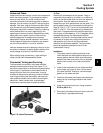
Oil Sentry
™
General
Some engines are equipped with an optional Oil
Sentry
™
oil pressure switch monitor. If the oil pressure
decreases below an acceptable level, the Oil Sentry
™
will either shut off the engine or activate a warning
signal, depending on the application.
The pressure switch is designed to break contact as
the oil pressure increases, and make contact as the oil
pressure decreases. At oil pressure above
approximately 3.0/5.0 psig, the switch contacts open.
Below this pressure, the switch contacts close.
On stationary or unattended applications (pumps,
generators, etc.), the pressure switch can be used to
ground the ignition module to stop the engine.
On vehicular applications (lawn tractors, mowers, etc.)
the pressure switch can only be used to activate a
warning light or signal.
NOTE: Make sure the oil level is checked BEFORE
EACH USE and is maintained up to the
‘‘FULL’’ mark on the dipstick. This includes
engines equipped with Oil Sentry
™
.
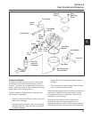
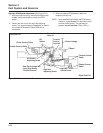
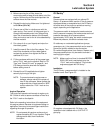
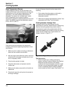
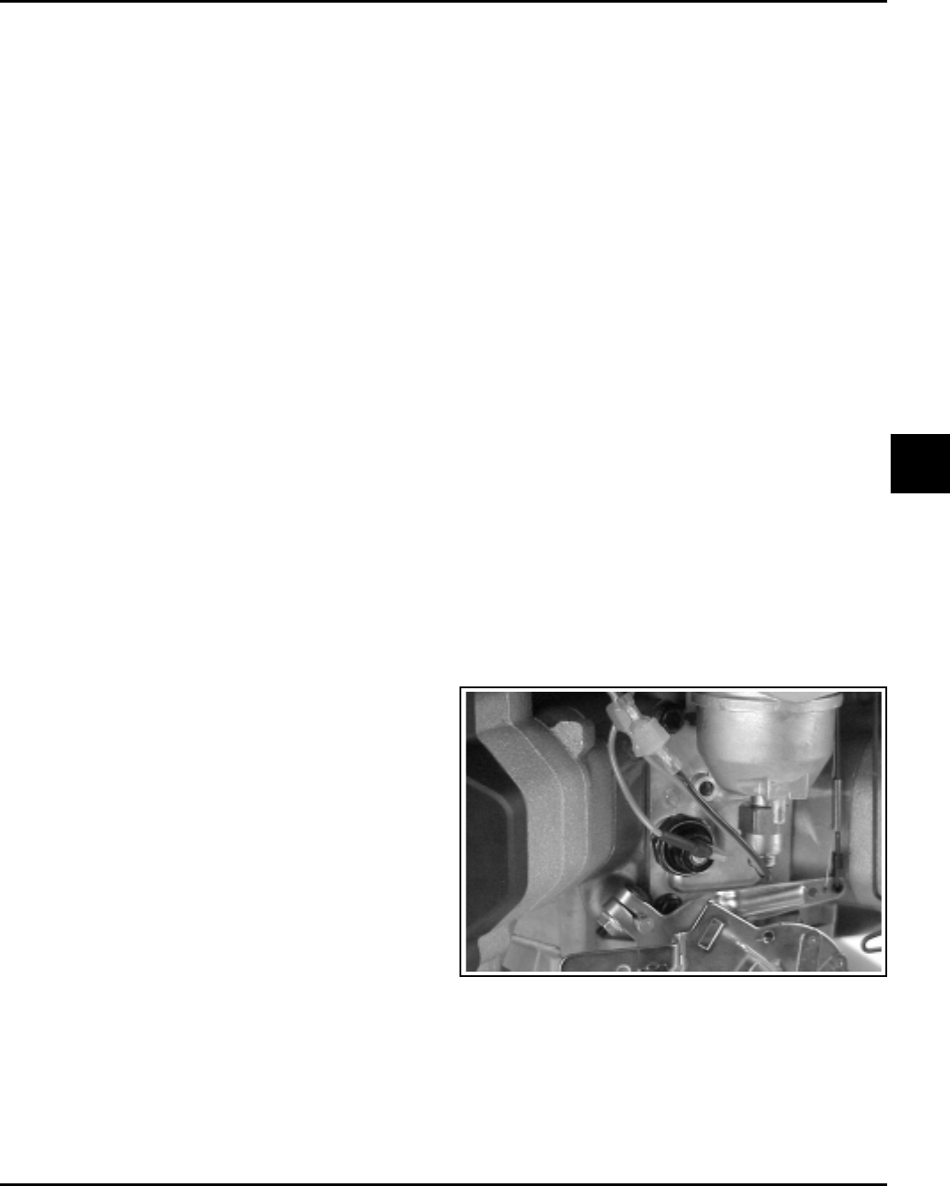
Installation
The Oil Sentry
™
pressure switch is installed on the
breather cover. See Figure 6-5.
Figure 6-5. Oil Sentry
™
Location.
On engines not equipped with Oil Sentry
™
the
installation hole is sealed with a 1/8-27 N.P.T.F.
pipe plug.