11.21
Section 11
Reassembly
11
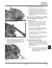
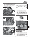
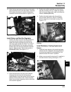
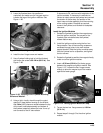
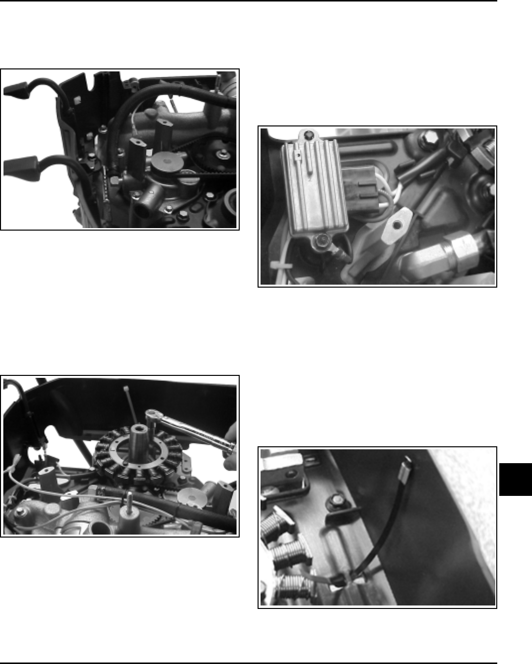
Figure 11-70. By-pass Hose Installation.
Install Stator and Rectifier-Regulator
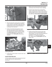
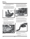
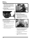
1. Position the stator onto the mounting bosses so
the leads are at the bottom, and directed out
toward the rectifier-regulator mount on the #1
side. Apply pipe sealant with Teflon
®
(not Teflon
®
tape) to the threads of the two stator mounting
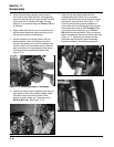
screws. Align the mounting holes and install the
two hex. flange screws. Torque each screw to
6.2 N·m (55 in. lb.). See Figure 11-71.
3. Position the rectifier-regulator onto the locating
stud with its cooling fins ‘‘up’’. Attach the ground
lead to the mounting screw, install and torque the
screw to 4.0 N·m (35 in. lb.).
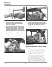
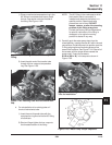
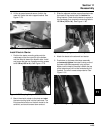
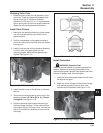
4. Position the stator leads under the retaining
tab, and down within the ‘‘channel’’ formed by
the two raised ribs in the blower housing. See
Figure 11-72.
12. Attach the by-pass hose to the fitting on the water
pump and secure with the hose clamp. The tangs
of the clamp should point outward. Completed
installation should look as shown in Figure 11-70.
Figure 11-72. Installed Rectifier-Regulator and Wire
Routing.
Install Radiators, Cooling System and
Hoses
1. Install the hose clamps on the remaining hoses,
inward from their respective mounting locations,
but where the tangs will be accessible for final
placement after the hose is in position.
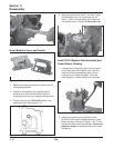
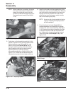
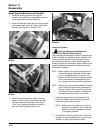
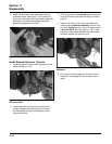
2. Make sure new metal tie strap is still in position in
the lower blower housing. See Figure 11-73.
Figure 11-73. Wire Tie Strap.
Figure 11-71. Torquing Stator Mounting Screw.
2. Check the terminal on the end of the violet B+
charging lead to be sure the locking tang is
angled upward. Insert the terminal into the center
location of the connector until it locks into place.
Attach the connector assembly onto the terminals
of the rectifier-regulator.


