


11.32
Section 11
Reassembly
1. Use equal parts of ethylene glycol (anti-freeze)
and water only. Distilled or deionized water is
recommended, especially in areas where the
water contains a high mineral content. Propylene
glycol based anti-freeze is not recommended.
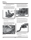
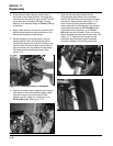
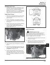
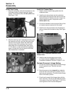
2. Fill the cooling system, through neck for radiator
cap, with the coolant mix. Allow the coolant to
drain into the lower areas. Fill the overflow
reservoir midway between the ‘‘Min. Level’’ and
‘‘Max. Level’’ marks, then install the radiator and
reservoir caps. See Figure 11-106.
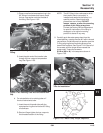
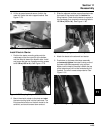
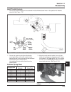
Reconnect Battery and Spark Plug Leads
Connect the leads to the spark plugs. Reconnect the
positive battery lead first, and the negative (-) lead last
when reconnecting the battery. See Figure 11-107.
Testing the Engine
It is recommended that the engine be operated on a
test stand or bench prior to installation in the
application.
1. Make sure all hardware is tightened, and hose
clamps are properly secured.
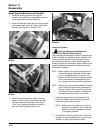
2. Set up the engine on a test stand. Install an oil
pressure gauge (Kohler Part No. 25 761 06-S is
recommended). Start the engine and check to be
certain that oil pressure (20 psi or more) is present.
Run for 5-10 minutes between idle and mid-range.
3. Check all cooling system components and joint
connections for leaks.
4. Make sure the maximum engine speed does not
exceed 3750 RPM (no load). Adjust the throttle,
choke controls and high speed stop as necessary.
Refer to the ‘‘Fuel System and Governor’’ section.
5. Place the throttle control into the ‘‘idle’’ or ‘‘slow’’
position and check the low idle speed (RPM).
Refer to section 5 if adjustment is required.
6. Stop the engine.
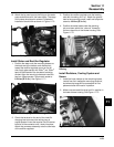
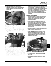
7. Remove the blower housing and recheck coolant
lever in reservoir. Coolant level should be
between the ‘‘Max. Level’’ and ‘‘Min. Level’’ marks.
Add coolant if required. See Figure 11-106.
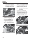
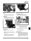
8. Reinstall the upper blower housing and screen
assembly. Secure with the four retainer straps.
Figure 11-106. Reservoir Levels.
3. Install the upper blower housing and screen
assembly. Secure with the four retainer straps.
See Figure 11-107.
Figure 11-107. Securing Retainer Straps and
Connecting Spark Plug Leads.