


11.29
Section 11
Reassembly
11
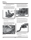
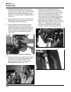
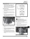
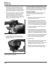
Install Throttle Controls
1. Connect the choke linkage from the carburetor into the choke actuator lever on the speed control bracket
assembly. See Figure 11-97.
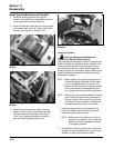
Washer,
flat (3)
Lever Throttle
Control (middle)
Lever,
Throttle
Actuator
(bottom)
Bracket,
Speed
Control
Spring,
Choke
Return
Nut,
M5x0.8
Lock
Figure 11-97. Throttle/Choke Control Bracket and Governor Lever Detail.
1
2
3
4
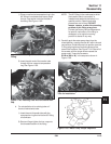
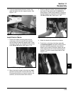
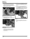
2. Connect the governor spring from the throttle
control pivot lever on the main bracket to the
appropriate hole in the governor lever, as indicated
in the following chart. Note that the
hole positions are counted outward from the
governor shaft.
Governor Spring Chart
Governor Lever
Hole No.
High Idle RPM
3888
3780
3672
3564
3456
3348
3240
3132
3024
4
3
3
3
2
2
2
2
1
Governor Spring
Color Code
Red
Purple
Black
Red
Purple
Green
Red
Clear
Red
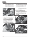
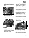
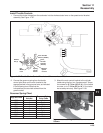
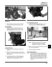
3. Attach the main control bracket to the cylinder
heads using the four hex. flange screws. Torque
the screws to 10.7 N·m (95 in. lb.) if the heads
are new, or to 7.3 N·m (65 in. lb.) if the holes
were used previously. See Figure 11-98.
Figure 11-98. Attaching Main Bracket with Four
Screws.