


10.11
Section 10
Inspection and Reconditioning
10
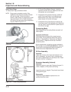
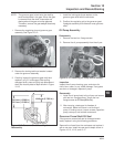
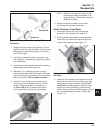
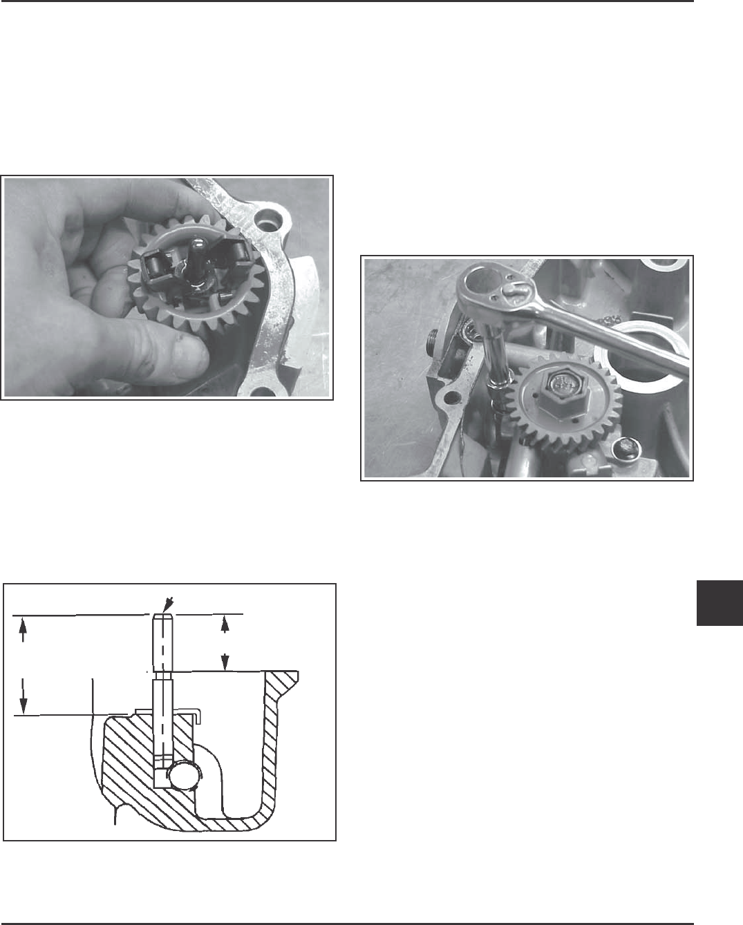
NOTE: The governor gear is held onto the shaft by
small molded tabs in the gear. When the gear
is removed from the shaft, these tabs are
destroyed and the gear must be replaced.
Therefore, remove the gear only if absolutely
necessary.
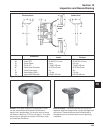
1. Remove the regulating pin and governor gear
assembly. See Figure 10-12.
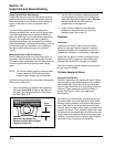
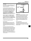
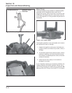
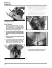
Figure 10-13. Governor Shaft Press Depth.
Reassembly.
Figure 10-12. Removing Governor Gear.
2. Remove the locking tab thrust washer located
under the governor assembly.
3. Carefully inspect the governor gear shaft and
replace it only if it is damaged. After pulling
damaged shaft, press or lightly tap replacement
shaft into closure plate to depth shown in Figure
10-13.
1. Install the locking tab thrust washer on the
governor gear shaft with the tab down.
2. Position the regulating pin to the governor gear/
flyweights assembly and slide both onto governor
shaft.
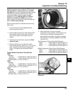
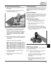
Oil Pump Assembly
Disassembly
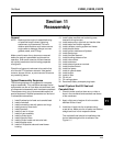
1. Remove the two hex. flange screws.
2. Remove the oil pump assembly from the oil pan.
Figure 10-14. Removing Oil Pump and Oil Pickup.
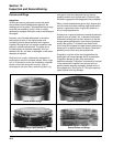
Inspection
Inspect the oil pump housing, gear, and rotors for
nicks, burrs, wear, or any visible damage. If any parts
are worn or damaged, replace oil pump.
Reassembly
1. Install the oil pump body to the oil pan and secure
with two hex. flange screws. Torque the hex.
flange screws to 6.7 N·m (60 in. lb.).
2. After torquing, rotate gear for freedom of
movement. Make sure there is no binding of
pump. If binding occurs, loosen screws, reposition
pump, retorque, and recheck movement.
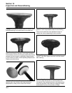
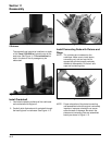
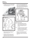
Governor Cross Shaft Oil Seal
If the governor cross shaft seal is damaged and/or
leaks, replace it using the following procedure.
Remove the oil seal from the crankcase and replace it
with a new one. Install the new seal to depth shown in
Figures 10-15, 10-16, and 10-17.
Governor Gear Shaft
19.40 mm (0.7368 in.)
34.0 mm (1.3386 in.)
33.5 mm (1.3189 in.)