


8.4
Section 8
Electrical System and Components
Electronic CD Ignition Systems
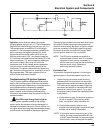
Operation of CD Ignition Systems
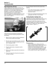
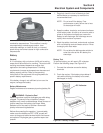
Capacitive Discharge with Fixed Timing
This system consists of the following components. See
Figure 8-3.
• A magnet assembly which is permanently affixed
to the flywheel.
• Two electronic capacitive discharge ignition
modules which mount on the engine crankcase.
• A kill switch (or key switch) which grounds the
modules to stop the engine.
• Two spark plugs.
The timing of the spark is controlled directly by the
location of the flywheel magnet group as referenced to
engine top dead center.
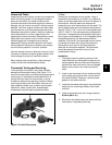
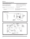
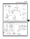
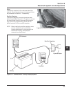
Figure 8-4. Electronic CD Ignition System (For Customer Connected Tractor Applications).
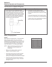
Kill Switch or ‘‘Off’’
Position of Key Switch
Spark
Plug
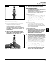
Magnet
Flywheel
.008/.012 in.
(.20/.30 mm)
Air Gap
Ignition
Modules
Figure 8-3. Capacitive Discharge Ignition System.
Oil Pressure
Safety Input
Rectifier-
Regulator
B+ and
Carburetor
Solenoid
Input
Ignition
Module
Input
Carburetor
Solenoid
Oil
Pressure
Safety
Red
Green
White
Ignition
Modules
Spark
Plugs
B+
Violet
Red
Starter and
Carburetor
Solenoid
Input
White
Red
Red
Spark
Advance
Module
(Optional)