


11.18
Section 11
Reassembly
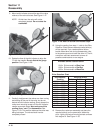
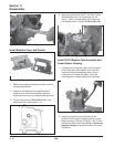
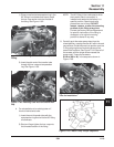
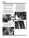
Figure 11-59. Installing O-Ring in Crankcase for
Water Pump.
NOTE: A mark or dot of paint applied to top of
pulley indicating the keyway location will
make installation easier.
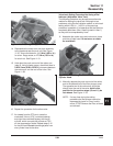
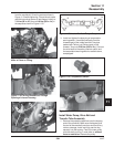
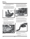
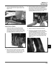
2. If the fitting for the by-pass hose in the water pump
was removed previously, apply pipe sealant with
Teflon
®
(not Teflon
®
tape) on the threads and install
onto the pump. Orient the fitting so the outlet points in
the 10 o'clock position as shown in Figure 11-58.
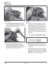
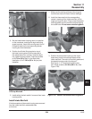
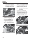
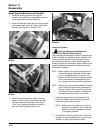
Figure 11-60. First Clamp and Hose Section
Installation.
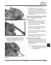
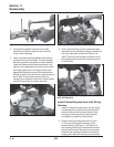
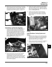
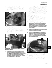
6. Slide the smaller diameter clamp onto the
extruded end of the formed metal tube and insert
this end of the tube into the hose section. Position
the tube so its formed offset leads down and away
from the outlet, perpendicular to the pump, as
shown in Figure 11-61. Install the clamp onto the
hose and position the tangs of the clamp parallel
to those of the first clamp.
Figure 11-61. Tube and Second Clamp Installed.
7. Holding the water pump in a raised position,
assemble the transfer tube to the 90° fitting in the
crankcase as follows:
a. For new/first time tube installation, or if ferrule
is loose on tube:
Figure 11-58. Fitting Position in Water Pump.
3. Check the sealing surfaces of the water pump
and crankcase. They must be clean and free of
any nicks or damage.
4. Place a new O-Ring in the groove of the crankcase,
and apply a small amount of grease in several
locations to hold it in place. See Figure 11-59. DO
NOT use RTV sealant in place of the O-Ring,
or attempt to reinstall a used O-Ring.
By-pass Hose
Fitting
5. Apply rubber lubricant to the inner surface of the
short hose section. Assemble the hose to the
outlet of the water pump and secure with the larger
diameter clamp. Orient the clamp so the tangs
extend down in the 5 to 6 o'clock position, towards
the impeller of the pump. See Figure 11-60.
5/04