


11.11
Section 11
Reassembly
11
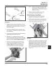
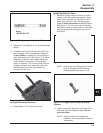
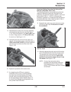
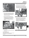
Figure 11-30. Installing Shim(s).
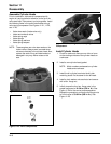
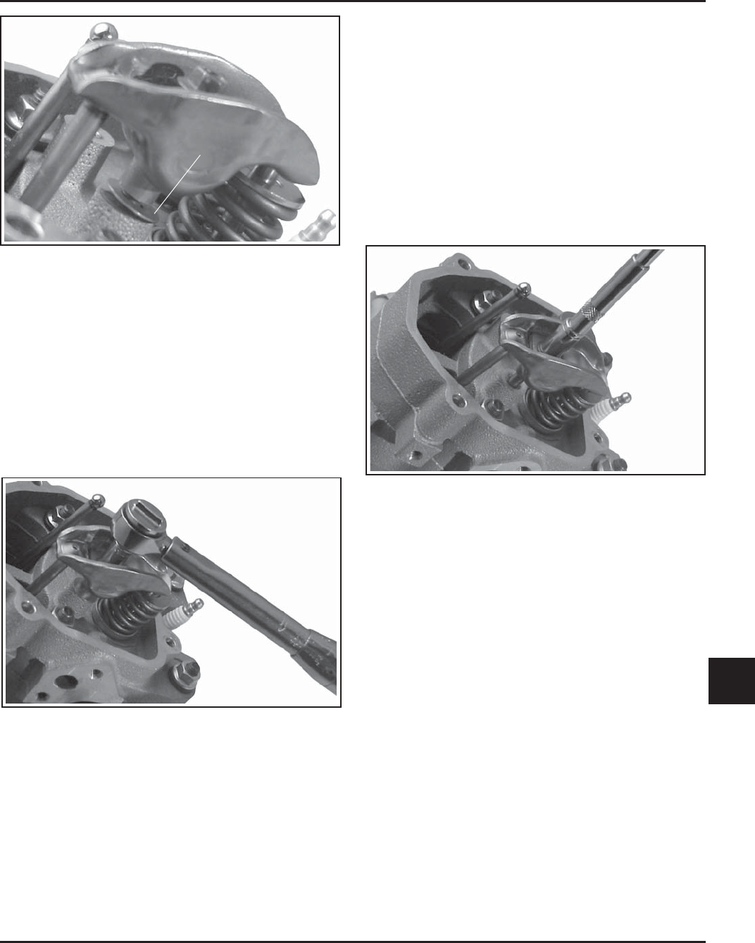
14. Reassemble the rocker arm and pivot assembly
to the head and seat the push rod. See Figure
11-30. Torque the fastener; 11.3 N·m (100 in. lb.)
for a hex. flange screw, or 17.3 N·m (153 in. lb.)
for a lock nut. See Figure 11-31.
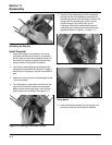
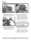
15. Hold down the push rod end of the rocker arm
(step 9). Using a feeler gauge, check that there is
0.03-0.3 mm (0.001-0.010 in.) clearance between
the rocker arm and the end of the valve. See
Figure 11-38.
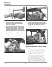
Figure 11-31. Torquing Rocker Arm.
16. Repeat the procedure for the other valve.
17. As viewed from the PTO end, rotate the
crankshaft 3/4 turn (270°) counterclockwise
and align the crankshaft keyway with the #2
cylinder, which now puts that cylinder at TDC
on the compression stroke. Repeat steps 3-15
for the #2 head. Do not interchange parts from
one cylinder head to the other.
Valve Lash Setting Procedure Not Using a Dial
Indicator (Adjustable Valve Train)
The following procedure may be used as an alternate
method for setting the valve lash. Although not as
precise as using the dial indicator method, a valve lash
setting within 0.001 in. - 0.003 in. of the previous
procedure is possible. It is imperative that the lifters be
completely bled down (See ‘‘Install Hydraulic Lifters’’)
so they can be compressed by hand.
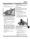
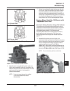
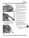
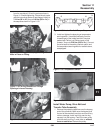
8. Assemble the rocker arms and rocker arm pivots
onto the cylinder head. Do not move or rotate
the crankshaft.
Figure 11-32. Mounting the Rocker Arm onto the
Cylinder Head.
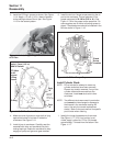
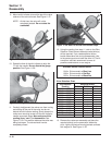
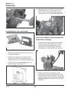
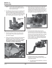
9. Manually depress the push rod end of the rocker
arm to the bottom/limit of the lifter plunger travel.
The opposite end of the rocker arm should be
directly over the end of the valve. Hold in this
position for the next two steps (10 and 11), do
not release. See Figure 11-33.
NOTE: If at any time during the setting
procedure the lifter plunger cannot be
depressed by hand or is very hard to
move, STOP! Remove the lifter, re-bleed
and reinstall.
Shim
5/04