


11.13
Section 11
Reassembly
11
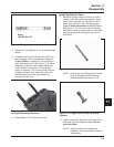
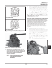
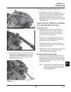
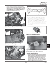
Figure 11-36. Installing Shim(s).
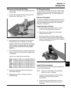
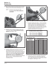
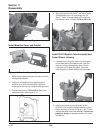
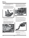
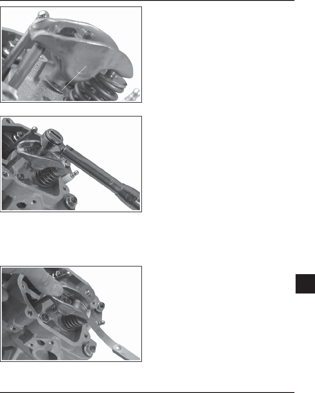
Figure 11-37. Torquing Rocker Arm.
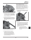
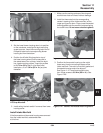
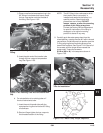
15. Hold down the push rod end of the rocker arm
(step 9). Using a feeler gauge, check that there
is 0.03-0.3 mm (0.001 to 0.010 in.) clearance
between the rocker arm and the end of the
valve. See Figure 11-38.
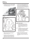
Figure 11-38. Checking for 0.001 in. - 0.010 in.
Clearance.
16. Repeat the procedure for the other valve.
17. As viewed from the PTO end, rotate the
crankshaft 3/4 turn (270°) counterclockwise and
align the crankshaft keyway with the #2 cylinder,
which now puts that cylinder at TDC on the
compression stroke. Repeat steps 8-15 for the #2
head. Do not interchange parts from one cylinder
head to the other.
Engines Serial No. 34065xxxxx and Higher
with “Non-Adjustable Valve Train”
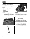
Install Rocker Arms
1. Apply grease to the contacting surfaces of the
rocker arms and rocker arm pivots. Install the
rocker arm pivots. Install the rocker arms and
rocker arm pivots on the one cylinder head and
start the two hex. flange screws.
2. Align rocker arm over valve and torque the hex.
flange screw to 11.3 N·m (100 in. lb.). Repeat for
the other rocker arm. See Figure 11-37.
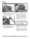
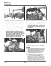
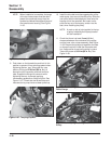
3. Use a spanner wrench or rocker arm lifting tool
(see Section 2) to lift the rocker arms and position
the push rods underneath.
4. Repeat steps 1-3 for the remaining cylinder. Do not
interchange parts from one cylinder head with
parts from the other cylinder head.
Reinstall Cylinder Drain Plugs
1. Reinstall the drain plugs into the cylinder heads if
they were removed in the disassembly procedure.
Apply pipe sealant with Teflon
®
(not Teflon
®
tape) to
threads and reinstall the plugs. Torque the plugs to
36.7 N·m (325 in. lb.).
NOTE: Early production engines contained steel
drain plugs. If encountered, replace with
later production brass (soft) plugs, Kohler
Part No. 66 139 01-S.
Shim
5/04