


11.16
Section 11
Reassembly
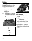
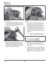
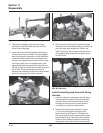
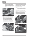
Figure 11-48. Torquing Thermostat Housing Screws.
4. Check that the gasket surfaces of the intake
manifold and cylinder heads are clean and free
of any nicks or damage.
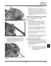
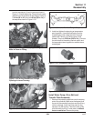
5. Install new intake manifold gaskets onto the port
surfaces of the cylinder heads. The use of gasket
adhesive to prevent movement, will aid installation.
Lower the intake manifold down and forward, into
position on the gaskets and cylinder heads. Install
and finger tighten the hex. flange screws in their
appropriate locations to prevent the manifold from
shifting, except for the two shorter length screws on
the #1 side. These screws secure the wiring
harness, the installation of which will follow, as well
as the final torquing of the intake manifold.
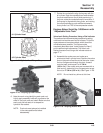
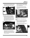
Figure 11-49. Intake Manifold Gasket in Place.
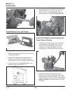
Figure 11-50. Intake Manifold in Place.
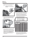
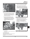
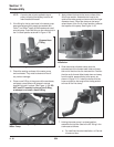
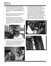
6. If the connector fitting for the by-pass hose was
removed from the manifold previously, reinstall it at
this time. Apply pipe sealant with Teflon
®
(not
Teflon
®
tape) onto the threads and tighten so the
fitting faces directly towards the long screw hole
on the #2 side.
Figure 11-51. Connector Fitting Orientation
with #2 Side Hole.
Install Coolant By-pass Hose with Wiring
Harness
1. Install the coolant by-pass hose, with the wiring
harness attached, onto the fitting of the intake
manifold. Secure with the hose clamp. Orient
the tangs of the clamp so they face outward
and slightly up, away from the flywheel.
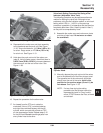
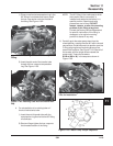
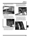
2. Route the wiring harness as shown in Figure
11-52, and out through the openings in the
blower housing. See Figure 11-53. Attach the
clip encasing the wiring harness and the shorter
ground lead to the #1 side, short screw location,
closest to the crankshaft. Attach the remaining
longer ground lead with the short screw furthest
5/04