


3-62 DISASSEMBLY, REASSEMBLY, INSPECTION, AND MAINTENANCE
Camshaft
•
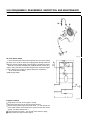
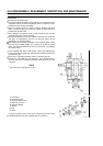
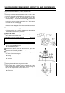
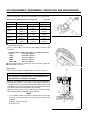
Using a micrometer, measure the camshaft journal in several places.
Camshaft Journal Diameter Service Limit (minimum) (Unit: mm)
PTO Side Flywheel Side
Type D Type G Type D, G
14.910 19.930 14.910
FE120
(0.5870 in) (0.7846 in) (0.5870 in)
15.910 24.930 15.910
FE170
(0.6264 in) (0.9815 in) (0.6264 in)
19.927 29.930 22.927
FE250
(0.7845 in) (1.1783 in) (0.9026)
22.927 29.930 22.927
FE290
(0.9026 in) (1.783 in) (0.9026 in)
22.927 34.930 22.927
FE350, 400
(0.9026 in) (1.3752 in) (0.9026 in)
If the measured value is smaller than the service limit, replace the
camshaft with a new one.
•
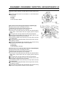
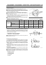
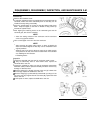
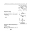
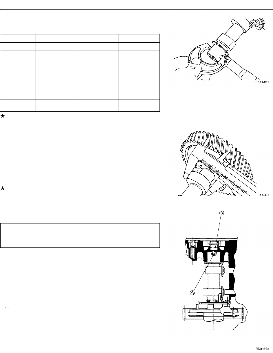
Using a vernier caliper, measure the overall height of the cam of the
camshaft.
Cam Overall Height Service Limit (minimum) - for Intake and Exhaust
FE120: 26.157 mm (1.0298 in)
FE170: 30.024 mm (1.1820 in)
FE250: 31.04 mm (1.2220 in)
FE290: 32.70 mm (1.2874 in)
FE350, 400: 33.24 mm (1.3087 in)
If the measured value is smaller than the service limit, replace the
camshaft with a new one.
Reassembly
•
Make sure to reinstall the camshaft with the oil pump removed.
CAUTION
If the camshaft is reinstalled with the oil pump attached to it,
it will cause serious damage to the engine.
•
Place the cylinder block on a base with the flywheel side facing down.
•
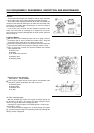
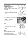
Reinstall the tappets or the HLAs in their original positions in
accordance with the intake and exhaust identification marks. Push
the tappets or the HLAs all the way against the cylinder head so that
they will not obstruct the installation of the camshaft.
•
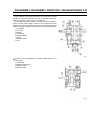
With the matching marks of the crankshaft gear and the camshaft
gear aligned, install the camshaft in the crankcase.
NOTE
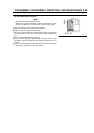
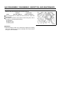
On the FE290, FE350, and FE400, verify that the tab [B] of the
oil pump is securely fitted into the groove [A] at the end of the
camshaft.
A: Groove at end of camshaft
B: Oil Pump Tab