


DISASSEMBLY, REASSEMBLY, INSPECTION, AND MAINTENANCE 3-19
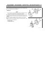
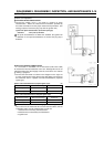
Charging System
The state of charge of the battery must be determined by measuring
the terminal voltage of the individual battery.
Individual Battery’s Terminal Voltage
Standard: 12 V
If the terminal voltage is below the standard, the battery must be
recharged.
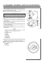
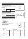
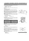
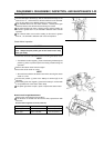
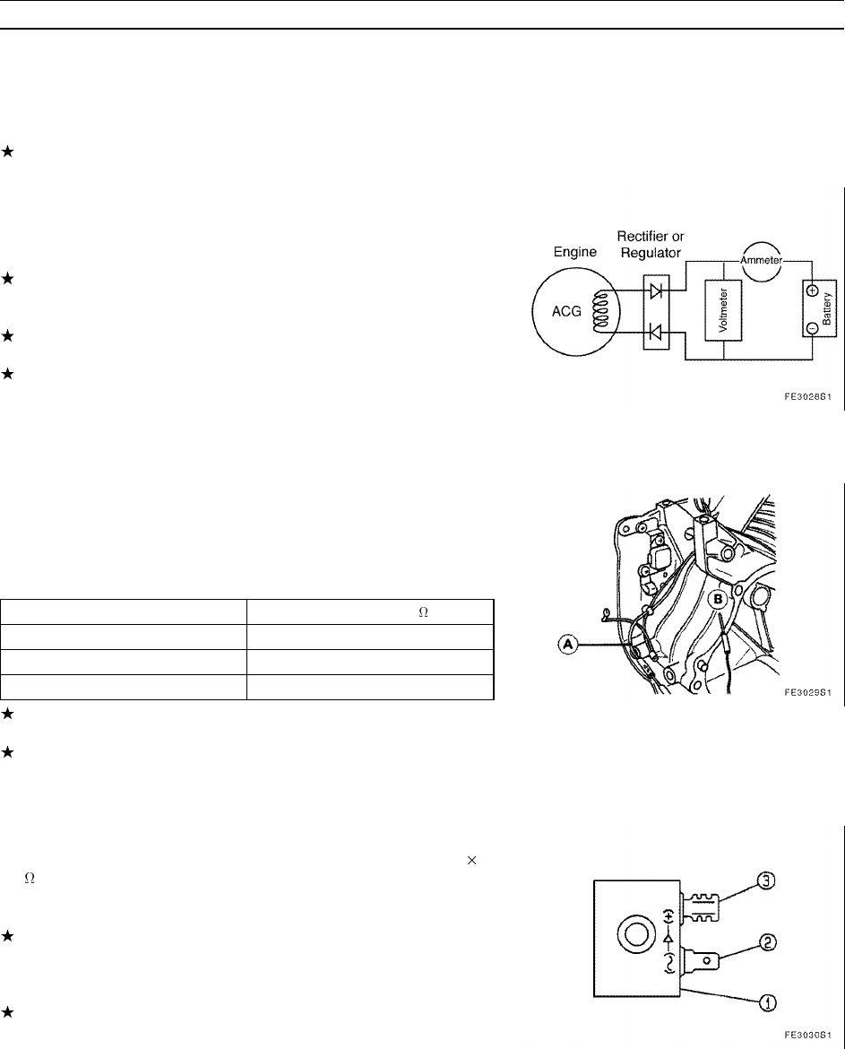
Charging System Inspection
Fully recharge the battery before inspecting the charging system.
•
Warm up the engine.
•
Connect a voltmeter to the battery terminals to measure the voltage.
When the engine speed is low, the voltmeter reads the battery voltage.
The voltage increases with an increase in the engine speed, although
the voltage fluctuation range will be within the specified values.
If the output voltage is higher than the specified value, the rectifier is
damaged or the lead is disconnected.
If the output voltage does not increase with an increase in the engine
speed, the rectifier is damaged or the alternator output is insufficient
for the applied load.
Rectifier Output Specified Voltage
Specified Value: Battery Voltage ~ 15 V
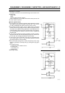
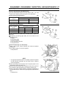
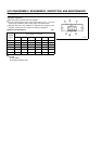
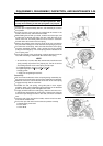
ACG Inspection
•
Disconnect the connectors from the alternator, connect a hand tester
to the lead of the charging coil and the ground in order to measure
the internal resistance of the charging coil.
ACG Internal Resistance
Coil Type Specified Range ( )
12 V – 2 A 0.40 ~ 0.67
12 V – 4 A 0.82 ~ 1.38
12 V – 13 A 0.26 ~ 0.44
If the measured value is out of the specified range, replace the
charging coil.
If the resistance of the coil is normal but there is no voltage, the rotor’s
magnetic force has diminished, so the rotor must be replaced.
A: ACG Lead (green/white)
B: Ground
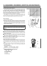
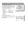
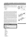
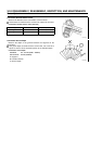
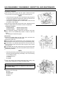
Rectifier Inspection
•
Set the resistance measurement range of the hand tester to R 1
k
.
•
Measure the resistance between the male and female connectors in
both positive and negative directions.
If the measured values are lower in one direction, and the other
direction is ∞, the rectifier is normal. The lower value should generally
be between 0 and the halfway point of the scale, although this could
vary from tester to tester.
If the measured value differs from the above, the rectifier is defective,
so it must be replaced with a good one.
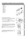
1. Rectifier
2. Male Connector
3. Female Connector