


3-16 DISASSEMBLY, REASSEMBLY, INSPECTION, AND MAINTENANCE
Ignition System
Igniter Inspection
Measure the internal resistance of the igniter.
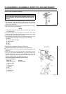
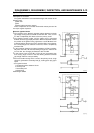
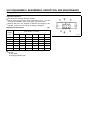
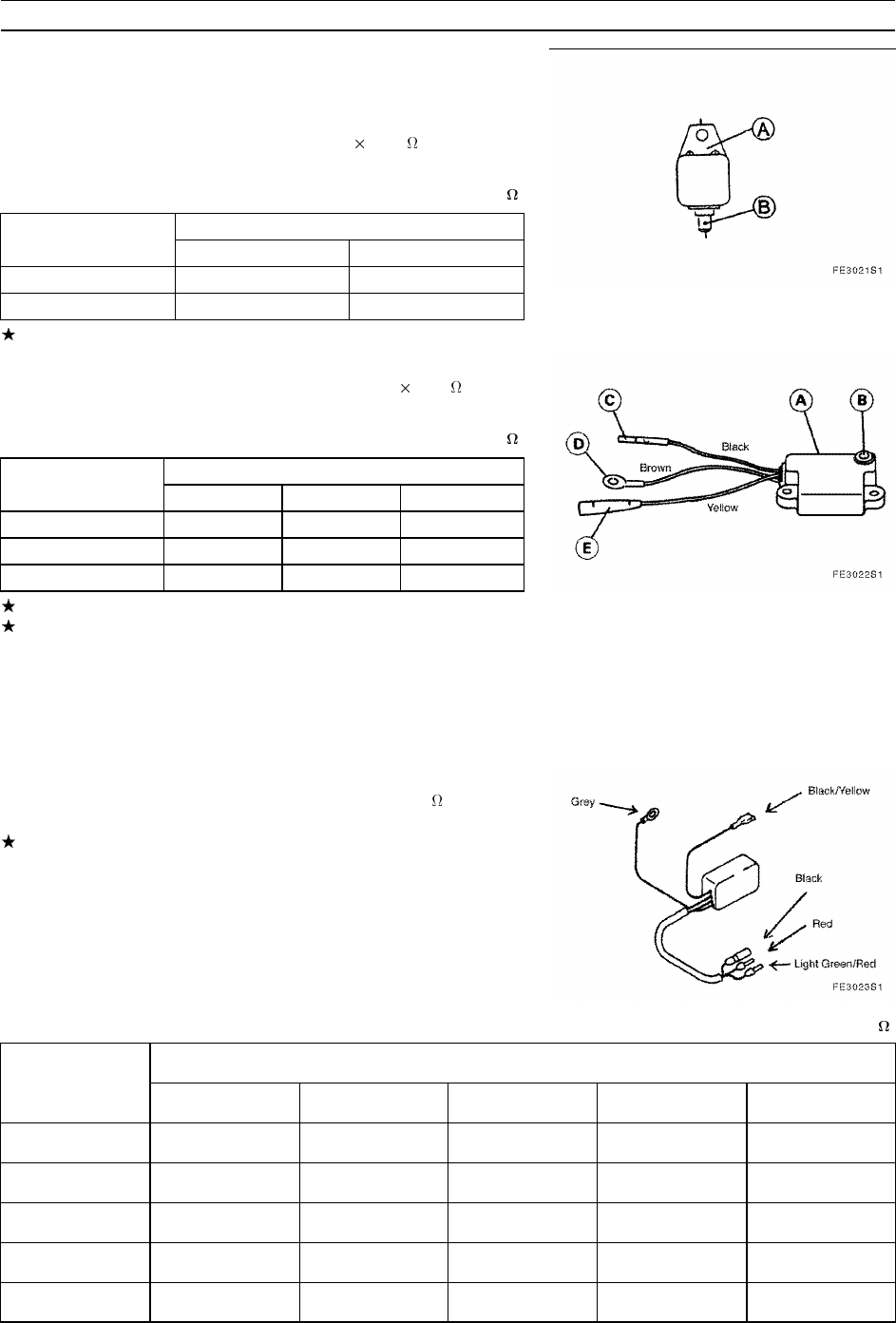
Individual Igniter Inspection
•
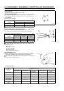
To test the individual igniter shown in the diagram on the right, set the
measurement range of the hand tester to R
100 and measure
the resistance.
Individual Igniter Resistance (k )
Tester negative (–) Tester positive (+) terminal
Terminal Case (A) Terminal (B)
Case (A) ––– 0.1 ~ 1.0
Terminal (B) 1~10 –––
If the measured value differs from the above, replace the igniter.
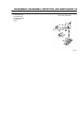
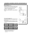
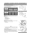
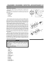
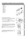
Igniter (with Oil Warning Light) Measurement
•
Set the measurement range of the hand tester to R 100 in order
to measure the resistance at the areas given in the table below.
Igniter (with Oil Warning Light) Resistance (k )
Tester Negative (–) Tester Positive (+) Terminal
Terminal D (brown) C (black) E (yellow)
D (brown) ––– 0.1 ~ 1.0 1~10
C (black) 1~10 ––– 5~20
E (yellow) 10 ~ ∞ 10 ~ ∞ –––
If the measured value differs from the table above, replace the igniter.
To inspect the oil warning light (LED), refer to the section on the
lubrication system.
A: Igniter
B: Oil Warning Light
C: Primary Terminal
D: Ground Terminal
E: Oil Level Sensor Terminal
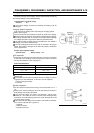
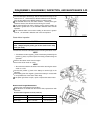
CDI Igniter Measurement
•
Set the measurement range of the hand tester to Rx100 in order to
measure the resistance at the areas given in the table below.
If the measured value differs from the table above, the igniter is
defective and it must be replaced.
CDI Igniter Resistance ( )
Tester Positive (+) Terminal
Tester
Negative (–)
Terminal
Black (switch) Red (exciter)
Light Green/
Red (pulser)
Grey (ground)
Black/Yellow
(ignition)
Black (switch) ––– 10 ~ ∞ 10 ~ ∞ 10 ~ ∞ 10 ~ ∞
Red (exciter) 200 ~ 2 k ––– 10 ~ ∞ 10 ~ ∞ 10 ~ ∞
Light Green/
Red (pulser)
10 ~ ∞ 10 ~ ∞ ––– 10 ~ ∞ 10 ~ ∞
Grey (ground) 1k~10k 200 k ~2 k 10 ~ ∞ ––– 10 ~ ∞
Black/Yellow
(ignition)
10 ~ ∞ 10 ~ ∞ 10 ~ ∞ 10 ~ ∞ –––