


DISASSEMBLY, REASSEMBLY, INSPECTION, AND MAINTENANCE 3-55
Crankshaft
Crankshaft Inspection
•
Inspect the crank pin and the journal for galling, wear, or rust.
If the crank pin exhibits damage as described above, carefully inspect
and repair the big end of the connecting rod, or replace the connecting
rod or the crankshaft with a new part.
•
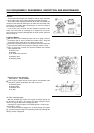
Inspect the crankshaft gear for abnormal wear or damaged teeth.
If the crankshaft gear is worn as described above, replace the
crankshaft gear with a new one.
•
Using a micrometer, measure the diameter of both journals of the
crankshaft, the diameter of the journal for the balancer link rod, and
the diameter of the crank pin in several places.
If the measured value is smaller than the service limit given below,
replace the crankshaft with a new one.
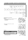
Crankshaft Journal Diameter Service Limit (minimum) (unit: mm)
FE120 FE170 FE250 FE290 FE350, 400
19.930 24.930 29.930 29.930 34.930
TPO Side
(0.7846 in) (0.9815) (1.1783 in) (1.1783 in)
(1.3752 in)
19.930 24.930 29.930 29.930 34.930
Flywheel Side
(0.7846 in) (0.9815) (1.1783 in) (1.1783 in)
(1.3752 in)
Journal
Diameter
46.924 46.924 49.924
Balancer Link Rod Journal – –
(1.8474 in) (1.8474 in) (1.9655 in)
25.944 28.944 33.944 35.444 37.444
Crankpin Diameter
(1.0214 in) (1.1395 in) (1.3394 in) (1.3954 in) (1.4742 in)
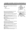
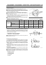
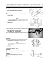
•
Using center support tools [B] as shown in the diagram, support both
ends of the crankshaft. Place a dial gauge [A] on the journal and
slowly turn the crankshaft to measure the fluctuation (the variance
between the maximum and minimum values) of the dial gauge, which
is the runout of the crankshaft.
Crankshaft Runout Service Limit (maximum)
Service Limit: 0.5 mm (0.02 in) (TIR)
If the measured value is greater than the service limit, replace the
crankshaft with a new one.
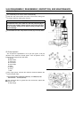
Crankshaft Axial Play Adjustment
If a part that affects the axial play has been replaced, the axial play
must be adjusted as described below. Shim adjustment is not available
on the FE120 and 170. Note: Except the FE170 for pump application.
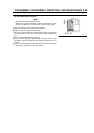
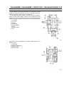
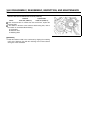
•
Place a gasket on the crankcase and measure and record the
distance from the gasket surface to the crankshaft gear surface
(measurement A).
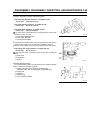
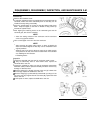
•
Measure and record the distance from the crankcase cover mating
surface to the end face of the crankshaft bearing inner race (mea-
surement B).
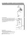
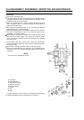
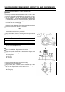
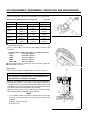
•
Place these measurements on the crankshaft shim selection table,
and trace the respective line.
•
Select the next thinner shim that appears on the shim selection table.
For example, on the FE290, if measurement [A] is 14.62 mm (0.576
in) and measurement [B] is 16.18 mm (0.637 in), the correct shim
thickness is t = 1.33 mm.
A: Measurement [A]
B: Measurement [B]
C: Crankcase Cover
D: Crankcase
E: Gasket