


DISASSEMBLY, REASSEMBLY, INSPECTION, AND MAINTENANCE 3-17
Ignition System
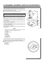
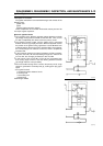
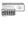
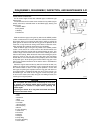
Controller (with Warning Light) Measurement
•
Set the measurement range of the hand tester to R 1k and
measure the resistance at the areas given in the table below.
Controller (without ground) Resistance (k )
Tester (–) Negative Tester Positive (+) Terminal
Terminal C (black) D (black/yellow)
C (black) ––– 50 ~∞
D (black/yellow) 1~7 –––
Controller (with ground) Resistance (k )
Tester (–) Negative Tester Positive (+) Terminal
Terminal C (black) D (black/yellow) E (brown)
C (black) ––– 50 ~ ∞ 50 ~ ∞
D (black/yellow) 1~7 ––– 50 ~ ∞
E (brown) 50 ~ ∞ 50 ~ ∞ –––
If the measured value differs from the table above, replace the
controller.
To inspect the oil warning light (LED), refer to the section on the
lubrication system.
A: Igniter
B: Oil Warning Light
C: Primary Terminal
D: Oil Level Sensor Terminal
E: Ground Terminal
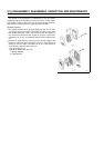
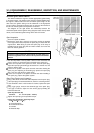
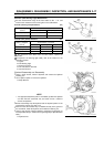
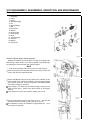
Flywheel Disassembly and Reassembly
•
Using a strap wrench, hold the flywheel and remove the flywheel
retaining nut.
•
Use a flywheel puller to remove the flywheel.
A: Strap Wrench
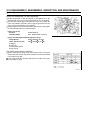
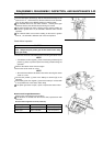
NOTE
If an appropriate flywheel puller is unavailable, position the flywheel
nut flush with the crankshaft end, and strike it with a mallet to
remove the flywheel.
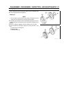
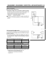
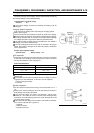
•
Before reassembly, wipe the flywheel and the tapered portion of the
crankshaft to remove any dust or oil.
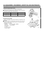
•
Make sure that the woodruff key is installed correctly in the groove of
the crankshaft, install the flywheel, and install the retaining nut.
•
Using a strap wrench, hold the flywheel, and tighten the flywheel nut
to the specified torque. (Refer to the Tightening Torque Specifications
table.)
A: Flywheel Nut