


3-32 DISASSEMBLY, REASSEMBLY, INSPECTION, AND MAINTENANCE
Valve System
•
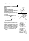
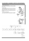
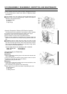
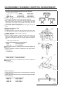
Using a wrench, secure the rocker arm pivot, and tighten the lock nut
to the specified torque. (Refer to the section on Tightening Torque
Specifications.)
On the FE290, use a pair of pliers to hold the adjustment bolt, and
tighten the lock nut to the specified torque. (Refer to the section on
Tightening Torque Specifications.)
A: Adjustment Bolt
B: Locknut
C: Gap Gauge
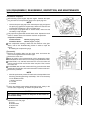
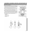
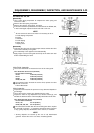
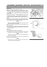
Automatic Compression Release (ACR) Device Inspection
The ACR reduces the compression of the cylinder in order to facilitate
the revolution of the crankshaft during the starting of the engine.
•
Detach the rocker cover and remove the spark plug.
•
Check whether the valves have the specified clearance.
•
Slowly turn the crankshaft in the direction of the engine rotation and
observe the movement of the exhaust valve [A] and the rocker arm
[B].
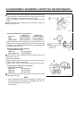
Immediately after the intake valve has closed, the rocker arm [B]
should push open the exhaust valve [A] to attain a lift that is greater
than the service limit given below. If the exhaust valve does not lift to
that height, the ACR that is provided on the camshaft is faulty. (Refer
to the section on Camshaft Inspection.)
Valve Lift Height Service Limit (minimum) by ACR - for Exhaust
FE120, 170, 250, 290: 0.6 mm (0.024 in)
FE350, 400: 1.0 mm (0.039 in)
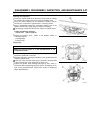
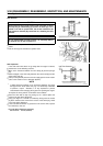
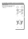
Valve Disassembly and Reassembly
For FE120, 170:
Disassembly
•
Place an appropriate receiving plate on the combustion chamber side
of the cylinder head.
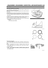
•
Using your thumbs, push down the spring retainer, slide the retainer
towards the side hole, and remove the retainer.
•
Remove the spring and the valve.
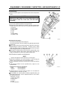
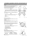
Reassembly
•
Verify that the valve seat is making proper contact and that the valve
stem moves smoothly in the guide.
•
The reassembly is the opposite of the disassembly.
•
Apply engine oil to the valve stem before reassembling the valve.
A: Spring Retainer
B: Side Hole
C: Sliding Direction