


3-8 DISASSEMBLY, REASSEMBLY, INSPECTION, AND MAINTENANCE
Governor Mechanism
Governor Gear Assembly Installation
CAUTION
Do not remove the governor gear assembly unless the parts
are to be replaced. The parts cannot be reused once they are
removed.
•
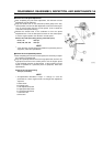
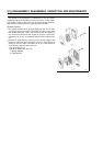
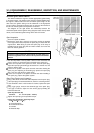
Use two screwdrivers of an appropriate size to remove the governor
gear assembly. Protect the surface of the gasket on the crankcase
cover to prevent it from becoming damaged during the removal of the
governor gear assembly.
•
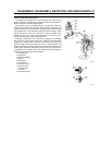
Install the sleeve on the governor gear assembly before the installa-
tion of the governor gear assembly.
NOTE
The sleeve cannot be installed after the governor gear assembly
has been installed.
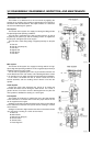
•
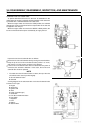
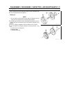
To install, first place the thrust washer over the shaft. Then, install
the governor gear assembly (with the sleeve attached) on the shaft
so that step [E] is fitted securely in groove [F].
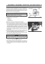
•
After installing the assembly, gently turn the governor by hand to make
sure that the governor weight and the sleeve move smoothly.
A: Sleeve
B: Governor Gear Assemblly
C: Thrust Washer
D: Shaft
E: Step
F: Groove
Governor Arm Installation (Setting the Governor)
•
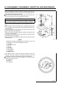
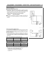
Install the throttle linkage and the spring on the governor arm.
•
Install the governor arm on the governor shaft and hand-tighten the
clamp nut.
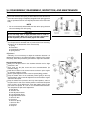
•
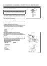
Loosen the clamp nut, and turn the end of the governor arm all
the way in the direction indicated below to keep the throttle valve
fully open. Meanwhile, insert the pin into the hole at the end of the
governor shaft, turn the end of the governor shaft all the way in the
direction indicated below, and tighten the clamp nut.
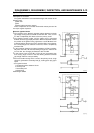
Direction of Rotation for Tightening the Governor Arm
and the Governor Shaft
FE120, 170: Clockwise
FE250, 290, 350, 400: Counterclockwise
1. Governor Shaft
2. Pin
3. Idling Posirion
4. Clockwise
5. Clip
6. End Hole
7. Governor Arm
8. Calmp Nut