


3-22 DISASSEMBLY, REASSEMBLY, INSPECTION, AND MAINTENANCE
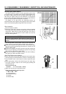
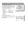
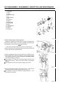
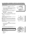
Starter System
1. Snap Ring
2. Collar
3. Spring
4. Clutch Assembly
5. Nut
6. Spring Washer
7. Bolt
8. Rear Cover
9. Washer
10. Brush Holder
11. Brush Spring
12. Brush
13. Yoke Assembly
14. Armature
15. Washer
16. Front Cover
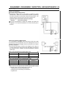
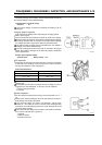
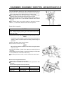
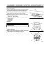
Solenoid (Starter Motor) Wiring Inspection
Although the following procedure gives the steps for inspecting the
shift-lever type starter motor, it can also be applied to the Bendix type
by replacing the word "solenoid" with "solenoid switch".
NOTE
First check the battery and make sure that it is fully charged.
•
Detach lead [A] from the solenoid terminal of the starter motor, and
keep it away from the solenoid terminal.
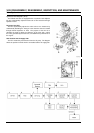
•
Detach lead [B] that connects the key switch to the solenoid, set the
measurement range of the tester to DC25 V, and connect it to lead [B]
and a ground on the unit. Turn the key switch to the START position
and read the voltage on the tester.
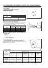
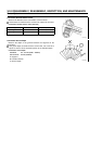
If the voltage is 0 or lower than the battery voltage, inspect the key
switch and the wiring. (Refer to the switch section of the Ignition
System.)
If the voltage is the same as the battery voltage, it is normal.
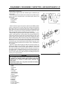
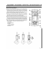
•
Set the measurement range of the tester to Rx1 , and read the
resistance between terminal [C] and a ground on the unit.
The solenoid is normal if the resistance is approximately 0 .Ifitis
not, replace the solenoid.