


3-54 DISASSEMBLY, REASSEMBLY, INSPECTION, AND MAINTENANCE
Crankshaft
Disassembly
•
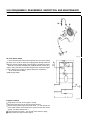
Remove the crankcase cover.
•
If axial play adjustment shims are provided for the crankshaft and the
camshaft, remove the shims and identify them so that they can be
installed correctly during reassembly.
•
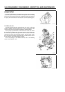
Place the cylinder block on a base so that the flywheel side faces
down. Keep the tappet (or the HLA on FE350 or 400) pushed up
towards the cylinder head.
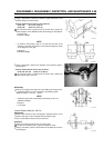
•
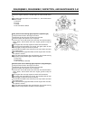
After aligning the matching marks on the crankshaft gear and the
camshaft gear, take out the camshaft.
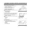
•
Remove the tappet (or the HLA on FE350 or 400) from the crankcase
and place an identification mark on it so that the tappet can be
reinstalled in its original position.
After taking out the HLA of the FE350 or 400, keep the side in which
the snap ring is visible upright. If it is placed on its side or upside
down, the oil that is sealed in the HLA unit could leak out, disabling
the HLA function.
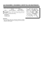
•
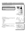
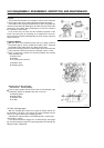
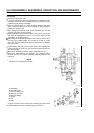
On the FE250, 290, 350, or 400 engine, remove the retaining nuts
[H] from the balancer guide [G], and pull out the balancer guide from
the crankcase [D].
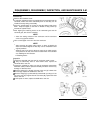
•
Remove the connecting rod bolts and the connecting rod cap.
•
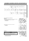
Remove the crankshaft from the crankcase. If it is equipped with a
balancer, take out the complete crankshaft assembly as is from the
crankcase.
NOTE
Be careful not to damage the oil seal.
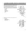
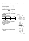
A: Crankshaft
B: Crankshaft Gear
C: Governor Drive Gear
D: Balancer Link Rod
E: Balancer Weight
F: Spacer
G: Key
H: Shim
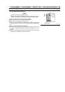
On Type G, however, the link rod on the crankshaft gear side cannot
be disassembled because the crankshaft gear is pressed in.