


DISASSEMBLY, REASSEMBLY, INSPECTION, AND MAINTENANCE 3-13
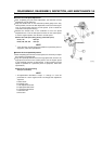
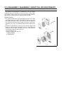
Ignition System
Description of Function
The ignition mechanism is the transistorized type and consists of the
following parts:
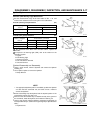
Ignition Coil
Igniter
Flywheel (with permanent magnet)
These components do not contain mechanical contact parts and do
not require regular inspection.
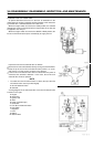
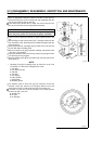
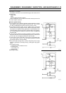
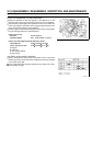
Electronic Ignition Device
•
The revolution of the flywheel generates voltage between terminals
[A] and [B], causing base current IB1 to flow from TR1. Then, current
IC1 that is amplified by TR1 flows to form the primary circuit.
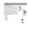
•
The flywheel revolves further and the voltage that is generated
between terminals [A] and [B] increases. When the flywheel reaches
the position of the ignition timing, signal base current IB2 flows from
automatic ignition advance circuit C to transistor TR2. At that instant,
the current changes into collector current IC2, which is amplified by
transistor TR2.
•
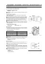
In the meantime, because the internal resistance of TR2 is consider-
ably lower than TR1, IB1 that was flowing through TR1 until then will
turn into IC2, thus changing its direction to flow via TR2.
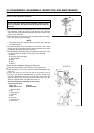
•
In this manner, base current IB1 of TR1 will not momentarily flow,
thus causing large current IC1 that was flowing between terminals
[A] and [B] until then to stop suddenly.
•
Due to the sudden change in the current in the primary circuit, a high
voltage is generated in secondary side [F], causing spark plug [G] to
spark.
A, B: Igniter Terminal
C: Automatic Ignition Advance Circuit
E: Primary Coil
F: Secondary Coil
G: Spark Plug
ESW: Engine Switch