


DISASSEMBLY, REASSEMBLY, INSPECTION, AND MAINTENANCE 3-33
Valve System
For FE250, 290, 350, 400:
Disassembly
•
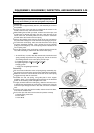
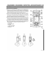
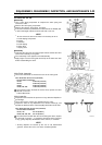
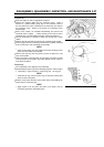
Use a valve spring compressor to compress the valve spring and
remove the collet.
•
Remove the valve spring compressor.
•
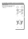
Remove the retainer, valve spring, and valve.
•
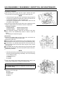
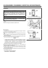
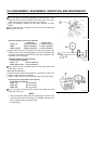
If the stem seal that is provided on the intake side of the FE290, 350,
or 400 is damaged, replace the stem seal with a new one.
NOTE
Do not remove the stem seal unless it is necessary to do so.
A: Valve Spring Compressor
B: Collet
C: Retainer
D: Valve Spring
E: Stem Seal
F: Spring Seat
Reassembly
•
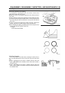
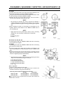
Verify that the valve seat is making proper contact and that the valve
stem moves smoothly in the guide.
•
The reassembly is the opposite of the disassembly.
•
Apply engine oil to the valve guide and the lip of the valve stem seal
before reassembling the valve.
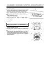
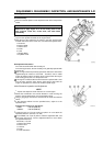
Valve Guide Inspection
•
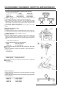
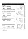
Use a bore micrometer to measure the bore of the valve guide.
Valve Guide Bore Service Limit (maximum)
- for both Intake and Exhaust
FE120: 5.562 mm (0.2190 in)
FE170: 5.562 mm (0.2190 in)
FE250: 6.065 mm (0.2388 in)
FE290, 350, 400: 7.065 mm (0.2782 in)
If the measured value exceeds the service limit, replace the valve
guide with a new one.
A: Bore Micrometer
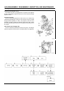
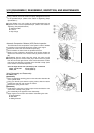
Valve Inspection
•
Inspect the valve head for the presence of any abnormal deposits or
gas leakage.
•
Use a wire brush to remove any deposits from the valve.
•
Inspect the valve for any depression in its contact surface [A], and
whether the thickness of the valve head [B] is below the service limit.
Valve Head Thickness Service Limit (minimum)
- for both Intake and Exhaust
FE120, 170: 0.5 mm (0.020 in)
FE250, 290, 350, 400: 0.6 mm (0.024 in)
If the valve head is smaller than the service limit given above, replace
the valve with a new one. 4. Inspect the valve stem for the presence
of any gummy deposits, discoloration due to seizure, or corrosion.
NOTE
Gummy deposits are caused by the use of old, deteriorated
gasoline. Instruct the user to use fresh, unleaded gasoline.