


DISASSEMBLY, REASSEMBLY, INSPECTION, AND MAINTENANCE 3-43
Cylinder Block and Crankcase Cover
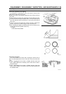
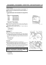
Cylinder Inspection
•
Inspect the cylinder wall for the presence of any scratches, the
cylinder exterior for any broken fins, and for any other damage.
If the cylinder has non-repairable damage, replace the cylinder block
with a new one.
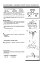
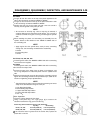
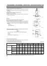
•
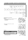
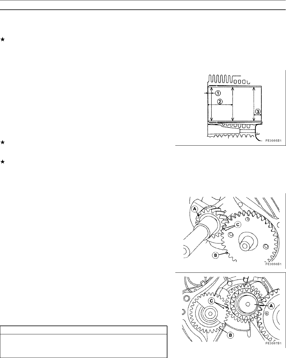
Using a cylinder gauge, measure the cylinder bore in the longitudinal
and latitudinal directions at the locations given in the diagram on the
right.
Cylinder Bore Service Limit (maximum)
FE120: 60.067 mm (2.3648 in)
FE170: 66.067 mm (2.6011 in)
FE250: 76.067 mm (2.9948 in)
FE290: 78.067 mm (3.0735 in)
FE350: 83.067 mm (3.2703 in)
FE400: 87.067 mm (3.4278 in)
Cylinder Bore Roundness (maximum)
Service Limit: 0.56 mm (0.0220 in)
If the measurement shows that even one area of the cylinder has a
greater bore or roundness than the service limit, bore the cylinder to
an oversize or replace the cylinder block.
The oversize piston and piston rings come in + 0.50 mm (0.020 in)
oversize.
1. 10 mm (0.394 in)
2. Center Point
3. 8 mm (0.315 in)
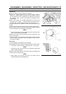
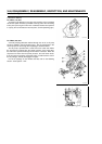
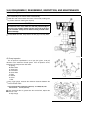
Crankcase Cover
Disassembly
•
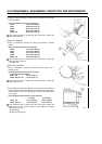
Drain the engine oil into an appropriate container.
•
Loosen the crankcase cover retaining bolts in the reverse sequence
of the tightening sequence given on the next page. Using a hammer
or a plastic mallet, gently tap on the crankcase cover at the area
where the cover is fastened to the engine, and remove the crankcase
cover.
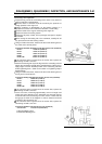
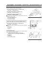
A: Crankshaft Gear
B: Camshaft Gear
C: Timing Mark
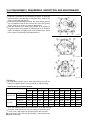
Reassembly
•
Clean the mating surface and place a new gasket on it.
•
Apply high-temperature grease to the area in which the oil seal lip
faces the rotating shaft. Apply engine oil to the bearing areas.
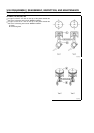
•
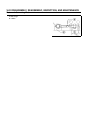
Verify that the respective timing marks on the crankshaft gear and the
camshaft gear, as well as on the crankshaft gear and the balancer
gear (optional equipment on FE170) are properly aligned.
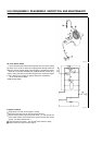
CAUTION
Make sure to remove the oil pump before installing the
camshaft. Serious damage to the engine will result if the
camshaft is installed with the oil pump in place.
A: Crankshaft
B: Timing Mark
C: Balancer Gear