


DISASSEMBLY, REASSEMBLY, INSPECTION, AND MAINTENANCE 3-29
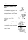
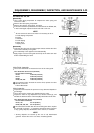
Valve System
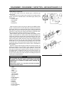
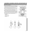
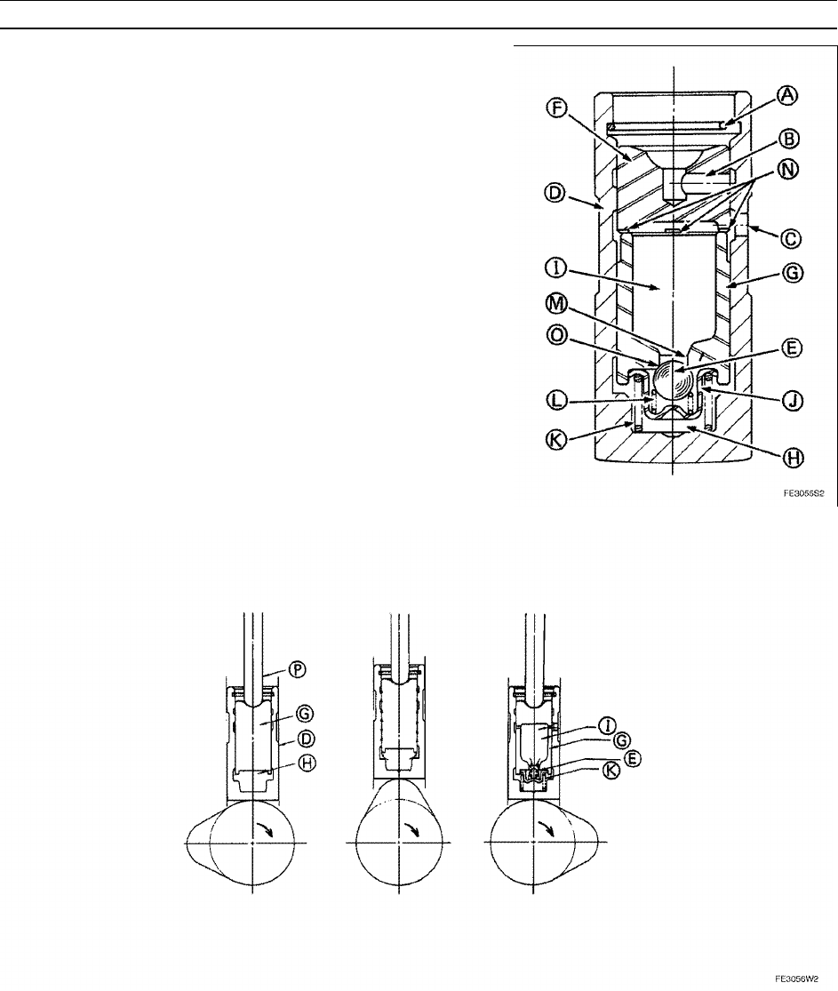
HLA Construction and Operation
•
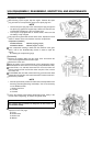
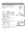
When the cam pushes the HLA upward, the oil in the high-pressure
chamber [H] tries to flow back to the oil pool [I] of the plunger [G]
by passing through the passage [M], but because the check ball [E]
closes the passage [M], the oil cannot flow back and it causes the
hydraulic pressure in the high-pressure chamber [H] to rise.
•
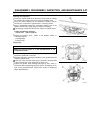
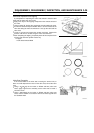
The oil of the high-pressure chamber [H] in which the hydraulic
pressure has risen leaks little by little through the gap (leak-down
rand) between the plunger [G] and the HLA body [D]. As a result, the
HLA shrinks slightly and pushes the pushrod [P] upward.
•
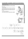
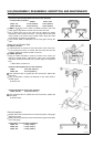
When the rotation of the cam causes the HLA to descend to the cam
base circle, the pressurized oil from the oil pump passes through the
oil hole [C] in the HLA body [D], travels through the oil groove [N] that
is cut into the socket [F], and enters the oil pool [I] in the plunger [G].
•
After filling the oil pool [I], the oil pushes open the check ball [E], and
flows into the lifter cage [J] and the high-pressure chamber [H], in
order to correct the valve train to achieve zero clearance.
A: Snap Ring
B: Oil Metering Hole
K: Plunger
L: Check Valve Spring
O: Check Valve Seat
P: Pushrod