


DISASSEMBLY, REASSEMBLY, INSPECTION, AND MAINTENANCE 3-21
Starter System
Starter Motor Construction
An FE series engine comes with a Bendix type or shift-lever type
starter motor.
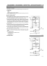
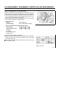
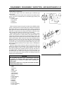
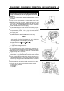
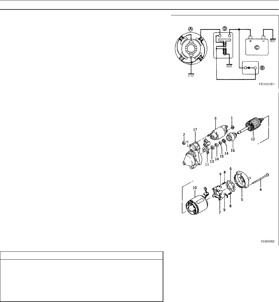
The electrical circuit of a starter motor consists of a key switch (engine
switch), solenoid (or solenoid switch on the Bendix type), battery, and
starter motor.
A: Starter Motor
B: Key Switch
C: Battery
D: Solenoind
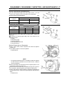
With the shift lever type, turning the key switch to the START position
causes a small amount of current to flow to the solenoid, which actuates
the plunger, which in turn moves the shift lever in order to engage the
pinion gear of the starter motor with the ring gear of the flywheel. At the
same time, a large amount of driving current flows to rotate the motor,
which transmits the rotational movement to the crankshaft.
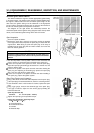
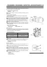
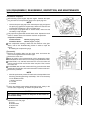
With the Bendix type, turning the key switch to the START position
causes a small amount of current to flow to the solenoid switch, thus
causing the solenoid to actuate and the solenoid switch to close. This
causes a large current to flow to the starter motor, enabling the starter
motor to start rotating. When the starter motor starts rotating, the pinion
moves by inertia to the ring gear (outer side) along the free-sliding
threads that are cut on the armature’s outer periphery and on the inside
of the pinion gear. As the pinion gear meshes with the ring gear in this
manner, the rotational movement of the starter motor is transmitted to
the crankshaft.
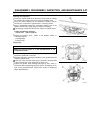
When the engine starts and the key switch is turned to the ON (run)
position, the current to the solenoid is cut off, causing the plunger and
the solenoid switch to return to their original positions. On the shift
lever type, the pinion gear separates from the ring gear and returns to
its original position, simultaneously with the return of the plunger. On
the Bendix type, the inertia of the ring gear causes the pinion gear
to return to the starter (inner side) along the free-sliding threads, thus
returning to its original position.
CAUTION
Do not operate the starter motor continuously for more than
5 seconds. Turn OFF the switch after 5 seconds, then allow
approximately 15 seconds to elapse before operating the
starter again.
Operating the starter for a long time could drain the battery
and burn the starter motor.
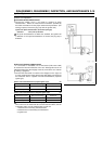
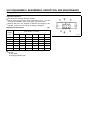
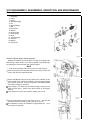
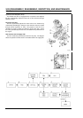
1. Nut
2. Nut
3. Solenoid
4. Bolt
5. Rear Cover
6. Insulator
7. Brush Holder
8. Brush Spring
9. Brush
10. Yoke Assembly
11. Shift Lever
12. Armature
13. Washer
14. Stopper
15. Snap Ring
16. Clutch Assembly
17. Front Cover