


DISASSEMBLY, REASSEMBLY, INSPECTION, AND MAINTENANCE 3-41
Piston and Connecting Rod
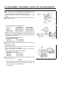
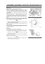
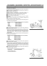
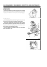
Connecting Rod Inspection
•
Inspect the big end of the connecting rod for wear or any traces of
seizure scratches or discoloration.
Abnormal wear or scratches could be caused by the presence of
foreign particles in the engine oil.
Vertical scratches or discoloration on the bearing surface is a
symptom that results from insufficient lubrication or overheating.
Clean the inside of the engine and change the engine oil.
Inspect and clean the cooling system.
Inspect the oil pump, oil filter, and oil passage and repair or replace
as needed.
When reusing the connecting rod or the crankshaft, carefully file off
any protrusions from their bearing surface.
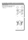
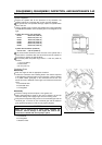
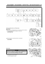
•
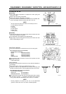
Using an inside micrometer, measure the bore of the bearing area of
the small end in several places.
Connecting Rod Small End Bearing Area Bore Service Limit (maximum)
FE120: 14.042 mm (0.5528 in)
FE170: 16.047 mm (0.6318 in)
FE250: 18.051 mm (0.7107 in)
FE290: 19.051 mm (0.7500 in)
FE350, 400: 20.051 mm (0.7894 in)
If the measured value is greater than the service limit, replace the
connecting rod with a new one.
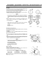
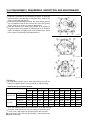
•
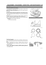
Mate the connecting rod cap to the big end of the connecting rod and
tighten the connecting rod bolts to the specified torque. Make sure to
apply engine oil to the threaded portion of the connecting rod bolts
before tightening them. (Refer to the section on Tightening Torque
Specifications.)
•
Using an inside micrometer, measure the bore of the bearing area of
the big end in several places.
Connecting Rod Big End Bearing Area Bore Service Limit (maximum)
FE120: 26.052 mm (1.0257 in)
FE170: 29.052 mm (1.1438 in)
FE250: 34.067 mm (1.3412 in)
FE290: 35.567 mm (1.4003 in)
FE350, 400: 37.567 mm (1.4790 in)
If the measured value is greater than the service limit, replace the
connecting rod with a new one.
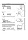
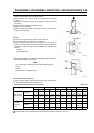
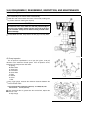
•
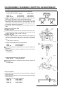
Insert a bar each, measuring approximately 100 mm in length and
almost the same diameter as the respective bore into both the big
and small ends of the connecting rod. Then, set the V block and the
dial gauge as shown in the diagram in order to measure the bend
and twist of the connecting rod.
If the measured value is greater than the service limit, replace the
connecting rod with a new one.
Connecting Rod Bend and Twist Service Limit (maximum)
Service Limit: 0.15/100 mm (0.006/100 in)
A: Big End Bearing Area
B: Small End Bearing Area