


C-4
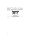
The GPS 75 will drive a remote alarm or relay that requires no more than
100 milliamps of current. (WARNING: Devices which draw current in
excess of 100 milliamperes may damage your unit and will void your
warranty. Consult the instructions included with the remote alarm or
relay for current drain information.)
To connect to a remote alarm system...
· Connect the BLUE harness lead to the negative side of a transistor
alarm or relay switch.
· Connect the positive side of the alarm or relay to the positive side
of the 5-40 volt DC power source.
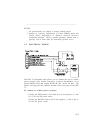
The GPS 75 may be connected to other marine electronics such as an
autopilot or plotter which use an NMEA 0180, NMEA 0182 or NMEA 0183
data interface. The unit can provide data for up to three NMEA
“listeners” simultaneously. Refer to installation instructions of these
devices for further information.
To connect the GPS 75 to an NMEA electronic device...
· Connect the BROWN harness lead to the NMEA “A” line of a two-
wire, shielded cable.
· Connect the BLACK harness lead to the NMEA “B” line of the
shielded cable.
· Connect the BLACK harness lead to the shield of the shielded
cable. (The opposite end of the shield should not be grounded.)
To connect the GPS 75 to an electronic device supplying RTCM
SC-104 data...
· Connect the WHITE harness lead to the output pin of the RTCM
device.
· Connect the BLACK harness lead to the ground pin of the RTCM
device.
· If the GARMIN Beacon Receiver is used, the Beacon Receiver
Page, (see Section 6.9), will tune the beacon frequency. Connect
the BROWN harness lead to the input pin (RS-232 RXD) of the
GARMIN Beacon Receiver.
Refer to GARMIN Beacon Receiver Operating Manual for connection
instructions.