Home
>
3. Helix P1
>
3.2 Helix System Overview
>
3.2.3 PXL Node Box Overview
3.2.3 PXL Node Box Overview
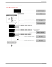
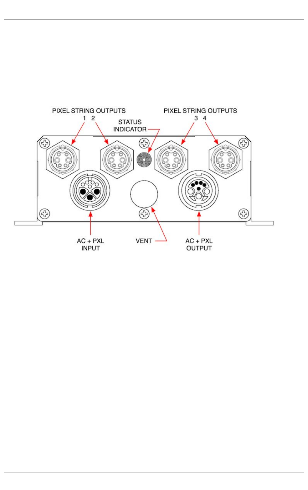
The PXL Node Box takes AC power and PXL data in, converts this to 24VDC and data out to four strings, and passes AC power and PXL data through to
the next PXL Node Box.
All connections are on one end panel of the box:
1.
AC + PXL INPUT
- black body -
This uses the standard PXL Cable Connector.
2.
AC + PXL OUTPUT
- white body -
This uses the standard PXL Cable Connector.
3.
PIXEL STRING OUTPUTS
- Four independent outputs, each can feed one P1 pixel string
4.
STATUS INDICATOR
-
Multicolor LED indicator
5.
VENT
-
IP65 gas
-
permeable microporous membrane vent
3. Helix P1 . 37
PXL System


