


Home
>
5. Power and Data Distribution
>
5.1 Hookup with a PXL Switch
5.1 Hookup with a PXL Switch
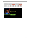
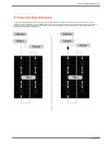
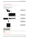
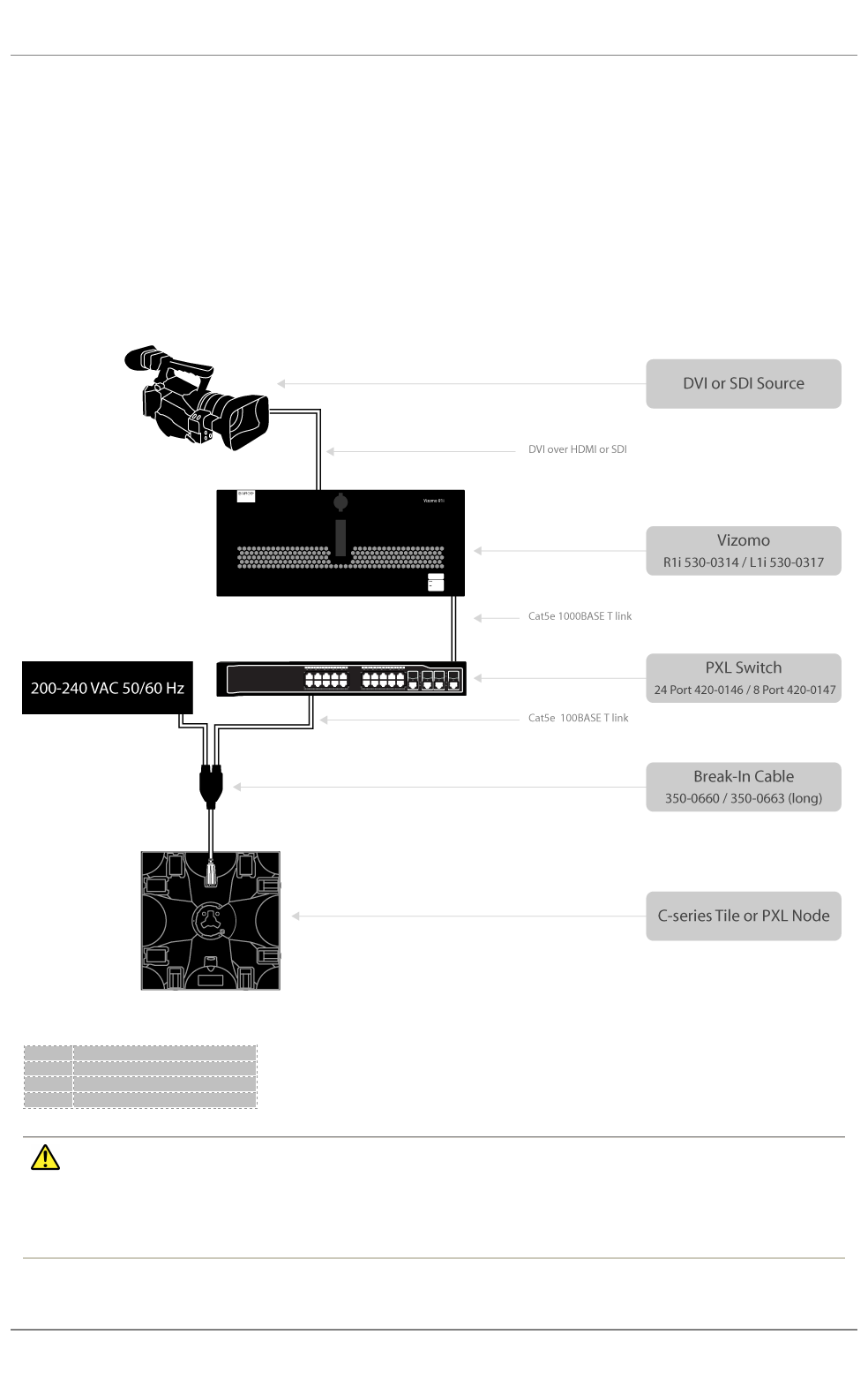
The image below illustrates the data flow of a C-series system from image capture to tile using a PXL switch for data and power routing.
Connections Checklist
●
DVI over HDMI or SDI (to a R1i only) signal connected to Vizomo capture card
● Network cable from a Vizomo PXL output to a switch PXL input
●
Break
-
in cable from switch PXL output to tiles. Observe maximum tiles per line limit
● 100-240V 50/60Hz VAC power source to Vizomo and PXL Switch(es)
● 200-240V 50/60Hz VAC power source to PXL tiles
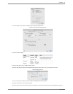
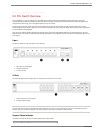
Observe the following data limits when setting up your C-series display.
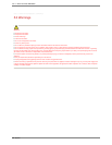
WARNING
• Never attach more than one PXL switch to a Vizomo output.
• Never attach more than one Vizomo PXL output to a switch.
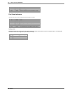
Fixture
Max panels per PDB
-5 output
C7
8
C11
16
C8v
25
5. Power and Data Distribution . 101
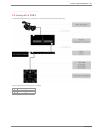
PXL System