


Home
>
5. Power and Data Distribution
>
5.4 PDB
-5 Overview
5.4 PDB
-
5 Overview
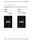
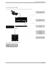
The PDB
-
5 has been designed primarily for rental and staging applications. The PDB
-5 handles the power and data distribution for C-
series tiles and P1
nodes.
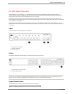
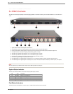
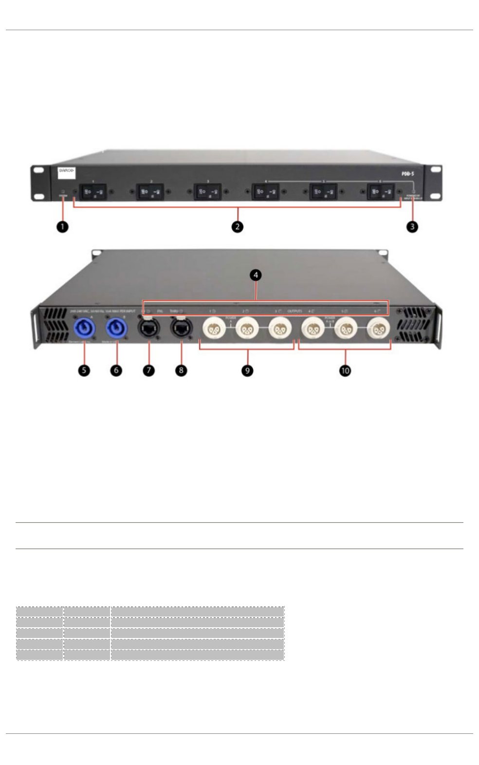
1. System Status Indicator. Indicates power and boot status.
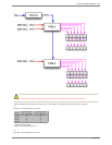
2. Circuit Breakers. 2-pole, 10A magnetic hydraulic circuit breakers for each of the 6 PXL cable outputs.
3. Power Input B Indicator. Indicates presence of power input through connector B on the back panel. Input B powers outputs 4-6.
4. Port Status Indicators. Indicates link integrity, disabled, activity, speed, full-duplex.
5. AC Power Input A 200-240 VAC, 50/60 Hz, 16 A max. via PowerCon (blue) connector.
6. AC Power Input B 200-240 VAC, 50/60 Hz, 16 A max. via PowerCon (blue) connector.
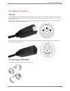
7. PXL Data Input via RJ45 EtherCon (shown) or optional Fiber Optic (not shown) connector.
8.
PXL Data Thru (pass through) via RJ45 EtherCon connector.
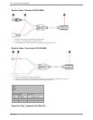
9.
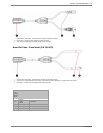
PXL Cable Outputs 1
-3. Integrated power and data outputs 1-3 via custom PXL Cable connectors. Powered by AC Power Input A.
10.
PXL Cable Outputs 4
-6. Integrated power and data outputs via custom PXL Cable connectors. Powered by AC Power Input A, or B if present.
NOTE
When first powered on, the PDB-5 will take several minutes to be fully booted and configured.
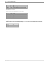
System Status Indicator
The LED on the front of the PDB
-5 or PXL Switch indicates system status as follows:
Port Status Indicators
The LEDs on the rear of the PDB
-5 or next to each port on a switch indicate each port's status as follows:
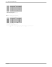
Color
State
Description
Off
Steady
System is not powered on
Green
Blinking
System is booting up
Green
Steady
System is operating correctly
Amber
Steady
System is receiving power, but not operating correctly
106 . 5. Power and Data Distribution
PXL System