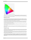
The CIE 1931 XYZ color space lies within a horseshoe shaped locus on a two dimensional coordinate system. Points within the color space are uniquely
defined with both an x and a y coordinate. These two values make up the "address" for a particular color. To find the yellow color referred to above,
locate the intersection of x=0.42 and y=0.51 on the chart. This also works in reverse where the coordinate of any color can be determined by locating the
color in the space, and then reading off the x and y values of that color.
Displaying True Color
These chromaticity coordinates allow us to define each color that we want to display. However, before we can begin to display a color we must define
the actual colors we have from the LEDs in the C-series panels. Due to the variability in manufacturing tolerances and availability of dyes used to create
LEDs, red, green, and blue LEDs are never going to perfectly match the CIE coordinates for true red, green, and blue. In order to create a color space that
the C
-series panel can display, each LED panel is measured by a specialized camera. This information allows the Vizomo processor to later compensate
with the correct combinations of actual LED source colors that are needed to hit our true CIE target colors.
If you look closely at a C-series panel displaying the color yellow you will notice that the red, green, and blue LEDs are all on at various intensities. Why
blue? The three primary colors, red, green, and blue, form a triangle on the CIE color chart. A contribution from each point of the triangle is needed to
achieve a target color within the space. Colors along the edge of the triangle may be created by only mixing the two colors at the ends of that edge, and
for each red, green, and blue primary, only that color contributes.
Our LED source color coordinates are fixed. We can only show a target color by adjusting (up or down) the brightness of our source colors. If we want a
less red color we can either turn red down or both green and blue up.
To create true yellow, choosing a point between red and green is not enough. We must also apply some blue to pull the point down a bit in the triangle and
reach the required target.
Similarly, if you create a pure red image on your computer you may see non red LEDs turn on when displayed on a color corrected LED screen. This is
because red LEDs are not the same color as pure red in CIE coordinates. As such, the color correction is compensating by adjusting the output to match
the color of the input.
Viewing True Color
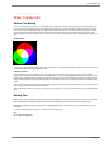
In the discussion above, the additive color model was used to determine what quantities of the primary colors were needed to produce a specified color.
To follow this model correctly, each primary color should be mixed optically. That is, the light generated by each primary color should be mixed so that they
overlap, and no amount of closer examination should be able to separate one from the other. An example of this would be taking three primary colored
lamps and projecting them onto a surface, where they mix.
To simplify their design, most direct view display devices such as CRTs, LCD and plasma panels, and LED displays, all place primary colored sub-pixels
side by side, rather than mixing them into one dot per pixel. By shrinking the geometric size of the sub pixels (the individual color components) and placing
them close enough together, at a specified viewing distance the eye can no longer resolve the individual sub pixels in space, and it blurs or fuses them
together into one pixel. This is called color convergence.
C
-series displays are designed to be viewed from a much larger distance than a TV or computer monitor, and as such, the minimum distance necessary
for color convergence to occur is much larger. Because of the ease at which C-series displays can be closer, it may appear as though the colors don't
look right when viewed from this distance. For example, as mentioned before, to display a specified "pure" red may require mixing in a small amount of blue
or green, depending on the chromaticity coordinate of the red sub-pixel being used. Observing this "pure" color from less than the minimum viewing
distance may seem incorrect, as the blue and green LEDs will clearly be illuminated. However, moving further away until color convergence is achieved
will resolve this issue.
30 . 2. C
-
series Tile
PXL System


