


8 - 47
– +
ELEC
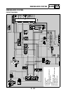
SIGNALING SYSTEM
YES
NO
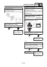
7. The coolant temperature warning light fails
to come on.
YES
NO
YES
NO
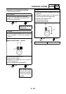
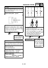
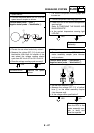
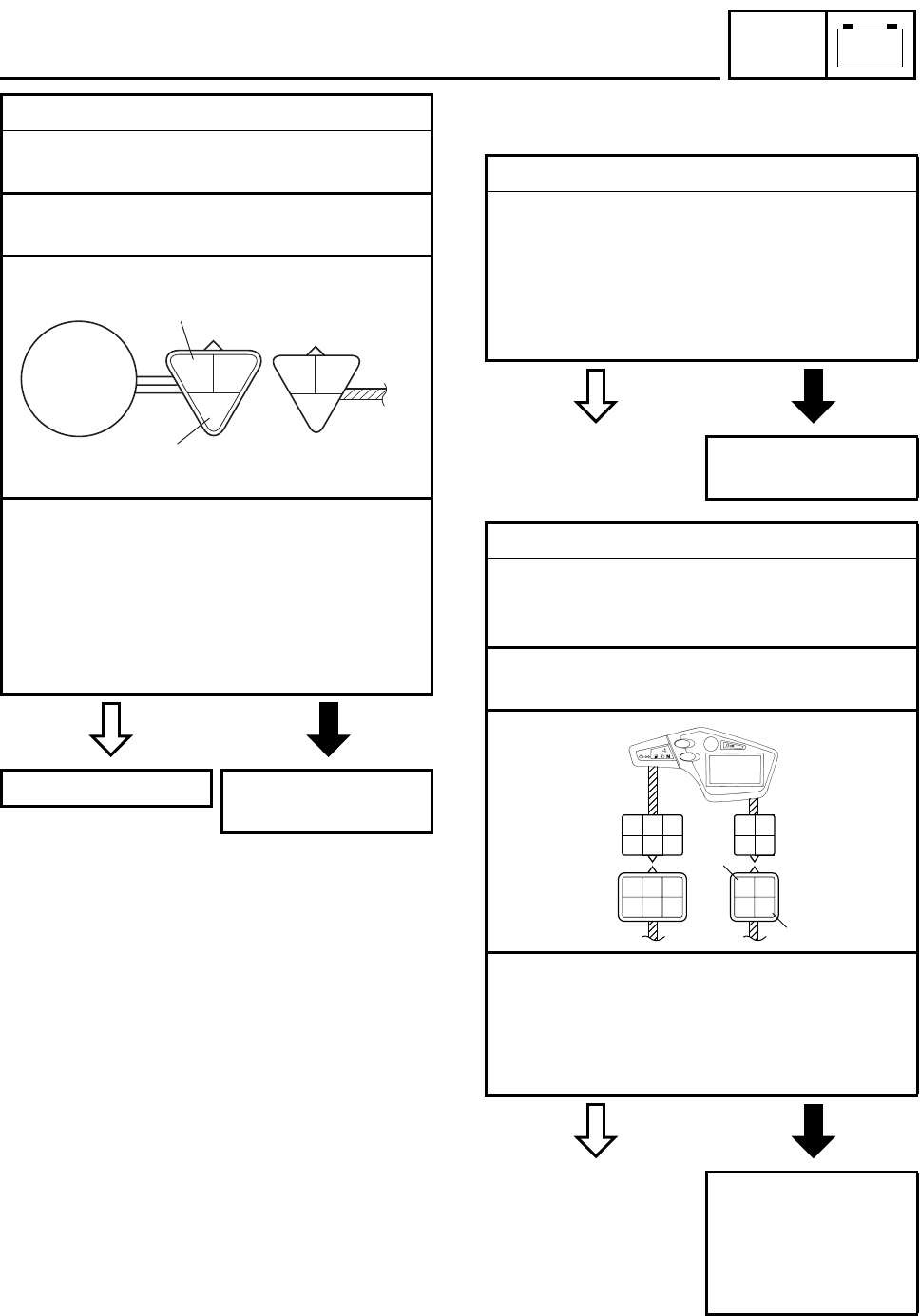
2. Speed sensor
• Connect the pocket tester (DC 20 V) to the
speed sensor coupler as shown.
Positive tester probe
→
pink
1
Negative tester probe
→
black/white
2
• Set the main switch to “ON”.
• Elevate the rear wheel and slowly rotate it.
• Measure the voltage (DC 5 V) of pink and
black/white. With each full rotation of the
rear wheel, the voltage reading should
cycle from 0.6 V to 4.8 V to 0.6 V to 4.8 V.
• Does the voltage reading cycle correctly?
This circuit is OK. Replace the speed
sensor.
P
O/R
B/W
L
W
B/L
1
2
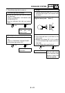
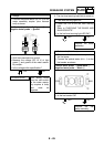
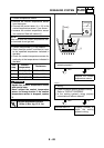
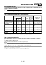
1. Coolant temperature warning light LED
• Check the LED of the coolant temperature
warning light.
Refer to “CHECKING THE BULBS AND
BULB SOCKETS”.
• Is the coolant temperature warning light
LED OK?
Replace the meter
assembly.
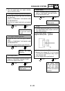
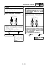
2. Voltage
• Connect the pocket tester (DC 20 V) to the
meter assembly coupler (wire harness
end) as shown.
Positive tester probe
→
yellow/blue
1
Negative tester probe
→
black/white
2
• Set the main switch to “ON”.
• Measure the voltage (DC 5 V) of yellow/
blue 1 on the meter assembly coupler
(wire harness end).
• Is the voltage within specification?
The wiring circuit
from the ECU to the
meter assembly cou-
pler is faulty and
must be repaired.
Dg
G/L
R/W
Ch
R/G
Y
B/W
Lg
G/W
Y/L
Ch R/G
Y
G
G/L
R/W
G/W
Y/L
B/W
Lg
1
2