


8 - 34
–+
ELEC
LIGHTING SYSTEM
EAS00788
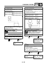
CHECKING THE LIGHTING SYSTEM
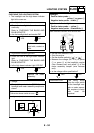
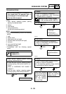
1. The headlight and the high beam indicator
light fail to come on.
YES
NO
YES
NO
YES
NO
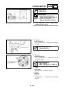
1. Headlight bulb and socket
• Check the headlight bulb and socket for
continuity.
Refer to “CHECKING THE BULBS AND
BULB SOCKETS”.
• Are the headlight bulb and socket OK?
Replace the head-
light bulb, socket or
both.
2. High beam indicator light LED
• Check the LED of the high beam indicator
light.
Refer to “CHECKING THE BULBS AND
BULB SOCKETS”.
• Is the high beam indicator light LED OK?
Replace the meter
assembly.
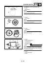
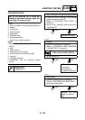
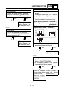
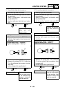
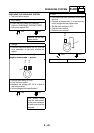
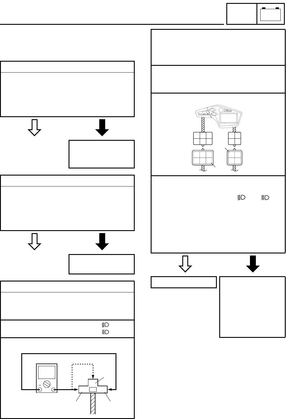
3. Voltage
• Connect the pocket tester (DC 20 V) to the
headlight and meter assembly couplers as
shown.
È
When the dimmer switch is set to “ ”
É
When the dimmer switch is set to “ ”
Headlight coupler (wire harness end)
DC 20 V
+
BY
G
2
1
3
È
É
Headlight
Positive tester probe
→
yellow
1 or green 2
Negative tester probe → black 3
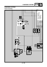
High beam indicator light
Positive tester probe → yellow 4
Negative tester probe → black/white 5
Meter assembly couplers (wire harness end)
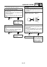
• Set the main switch to “ON”.
• Start the engine.
• Set the dimmer switch to “” or “”.
• Measure the voltage (DC 12 V) of yellow
1
or green
2
at the headlight coupler
(wire harness end) and yellow
4
at the
meter assembly coupler (wire harness
end).
• Is the voltage within specification?
This circuit is OK. The wiring circuit
from the main switch
to the headlight cou-
pler or meter assem-
bly couplers is faulty
and must be
repaired.
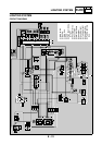
Dg
G/L
R/W
Ch
R/G
Y
B/W
Lg
G/W
Y/L
Ch R/G
Y
G
G/L
R/W
G/W
Y/L
B/W
Lg
4
5