


7 - 15
FI
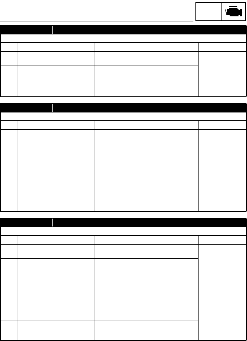
FUEL INJECTION SYSTEM
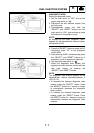
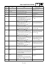
Fault code No. 16 Symptom The throttle position sensor is detected stuck.
Used diagnostic code No. 01 (throttle position sensor)
Order Item/components Check or maintenance job Restore method
1 Defective throttle position sensor Replace the sensor if it is defective.
Refer to “THROTTLE BODY ASSEMBLY”.
Reinstated by start-
ing the engine, oper-
ating it at idle, and
then racing it.
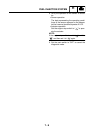
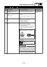
2 Throttle position sensor installation Execute the diagnostic mode. (Code No. 01)
Check the sensor for looseness or pinching.
Check that the sensor is installed in the specified
position. Refer to “THROTTLE BODY ASSEM-
BLY”.
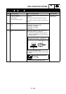
Fault code No. 19 Symptom Open circuit is detected in the input wire from the sidestand switch to the ECU.
Used diagnostic code No. 20 (sidestand switch)
Order Item/components Check or maintenance job Restore method
1 Coupler connections
ECU coupler
Blue/Black connector
Check the couplers for any pins that may have
pulled out.
Check that the couplers are securely locked.
If necessary, repair the coupler or securely con-
nect it.
If the transmission is
in gear, it is rein-
stated by retracting
the sidestand.
If the transmission is
in neutral, it is rein-
stated by reconnect-
ing the wiring.
2 Open or short circuit in the wire har-
ness
Repair or replace if there is an open or short cir-
cuit between the ECU and sidestand switch.
Blue/Black
3 Defective sidestand switch Execute the diagnostic mode. (Code No. 20)
Replace the switch if it is defective.
Refer to “CHECKING THE SWITCHES” in chap-
ter 8.
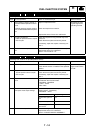
Fault code No. 21 Symptom Open or short circuit is detected from the coolant temperature sensor.
Used diagnostic code No. 06 (coolant temperature sensor)
Order Item/components Check or maintenance job Restore method
1 Coolant temperature sensor instal-
lation
Check the sensor for looseness or pinching. Reinstated by set-
ting the main switch
to “ON’.
2 Coupler connections
Coolant temperature sensor cou-
pler
ECU coupler
Check the coupler for any pins that may have
pulled out.
Check that the couplers are securely locked.
If necessary, repair the coupler or securely con-
nect it.
3 Open or short circuit in the wire har-
ness
Repair or replace if there is an open or short cir-
cuit between the wire harnesses.
Black/Blue - Black/Blue
Green/Red - Green/Red
4 Defective coolant temperature sen-
sor
Execute the diagnostic mode. (Code No. 06)
Replace the sensor if it is defective.
Refer to “COOLING SYSTEM” in chapter 8.