


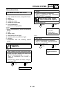
8 - 43
– +
ELEC
SIGNALING SYSTEM
YES
NO
YES
NO
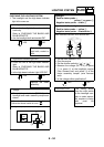
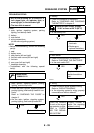
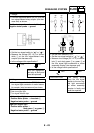
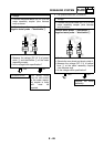
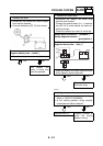
6. Voltage
• Connect the pocket tester (DC 20 V) to the
turn signal/hazard relay coupler (wire har-
ness end) as shown.
Positive tester probe
→
brown/white
1
Negative tester probe
→
ground
• Set the main switch to “ON”.
• Set the turn signal switch to “” or “”.
• Measure the voltage (DC 12 V) of brown/
white 1 at the turn signal/hazard relay
coupler (wire harness end).
• Is the voltage within specification?
The turn signal/haz-
ard relay is faulty and
must be replaced.
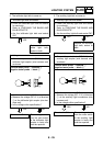
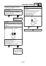
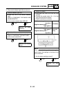
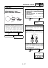
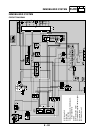
7. Voltage
• Connect the pocket tester (DC 20 V) to the
turn signal light connector or meter assem-
bly coupler (wire harness end) as shown.
È
Front turn signal light
É
Rear turn signal light
Ê
Turn signal indicator light
Left turn signal light
Positive tester probe
→
chocolate
1
Negative tester probe
→
ground
Right turn signal light
Positive tester probe
→
dark green
2
or green
3
Negative tester probe
→
ground
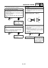
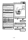
• Set the main switch to “ON”.
• Set the turn signal switch to “” or “”.
• Measure the voltage (DC 12 V) of choco-
late 1 and dark green 2 or green 3 at
the turn signal light connectors or meter
assembly coupler (wire harness end).
• Is the voltage within specification?
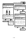
This circuit is OK. The wiring circuit
from the turn signal
switch to the turn sig-
nal light connectors
or meter assembly
coupler is faulty and
must be repaired.
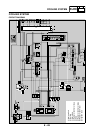
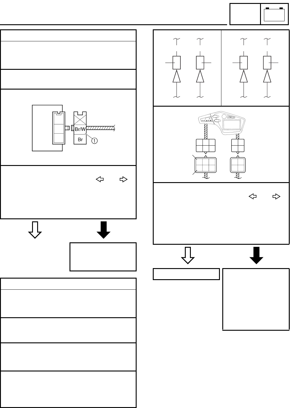
Ch Dg Ch G
3121
ÈÉ
Dg
G/L
R/W
Ch
R/G
Y
B/W
Lg
G/W
Y/L
Ch R/G
Y
G
G/L
R/W
G/W
Y/L
B/W
Lg
1
3
Ê