


8 - 30
– +
ELEC
CHARGING SYSTEM
EAS00775
NO
YES
EAS00776
YES
NO
EAS00779
YES
NO
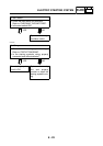
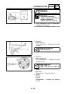
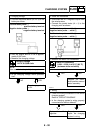
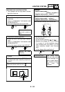
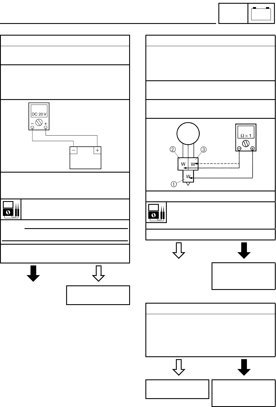
3. Charging voltage
• Connect the pocket tester (DC 20 V) to the
battery as shown.
Positive tester probe
→
positive battery terminal
Negative tester probe
→
negative battery terminal
• Start the engine and let it run at approxi-
mately 5,000 r/min.
• Measure the charging voltage.
Charging voltage
14.0 V at 5,000 r/min
NOTE:
_
Make sure the battery is fully charged.
• Is the charging voltage within specifica-
tion?
The charging circuit
is OK.
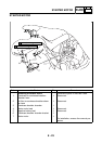
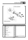
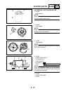
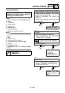
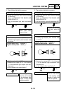
4. Stator coil resistance
• Disconnect the A.C. magneto coupler from
the wire harness.
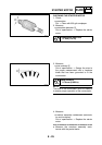
• Connect the pocket tester (
Ω
×
1) to the
charging coils as shown.
Positive tester probe
→
white
1
Negative tester probe
→
white
2
Positive tester probe
→
white
1
Negative tester probe
→
white
3
• Measure the stator coil resistances.
Stator coil resistance
0.224 ~ 0.336
Ω
at 20 °C (68 °F)
(between white and white)
• Is the stator coil OK?
Replace the crank-
shaft position sensor/
stator assembly.
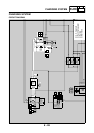
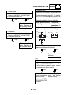
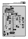
5. Wiring
• Check the wiring connections of the entire
charging system.
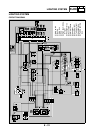
Refer to “CIRCUIT DIAGRAM”.
• Is the charging system’s wiring properly
connected and without defects?
Replace the rectifier/
regulator.
Properly connect or
repair the charging
system’s wiring.