


8 - 42
–+
ELEC
SIGNALING SYSTEM
EAS00799
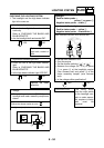
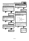
3. The turn signal light, turn signal indicator
light or both fail to blink.
YES
NO
YES
NO
YES
NO
YES
NO
YES
NO
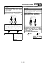
1. Turn signal indicator light bulb and socket
• Check the turn signal light bulb and socket
for continuity.
Refer to “CHECKING THE BULBS AND
BULB SOCKETS”.
• Are the turn signal light bulb and socket
OK?
Replace the turn sig-
nal light bulb, socket
or both.
2. Turn signal indicator light LED
• Check the LED of the turn signal indicator
light.
Refer to “CHECKING THE BULBS AND
BULB SOCKETS”.
• Is the turn signal indicator light LED OK?
Replace the meter
assembly.
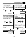
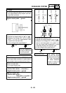
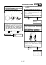
3. Turn signal switch
• Check the turn signal switch for continuity.
Refer to “CHECKING THE SWITCHES”.
• Is the turn signal switch OK?
Replace the left han-
dlebar switch.
4. Hazard switch
• Check the hazard switch for continuity.
Refer to “CHECKING THE SWITCHES”.
• Is the hazard switch OK?
Replace the left han-
dlebar switch.
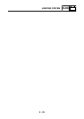
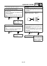
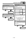
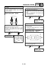
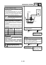
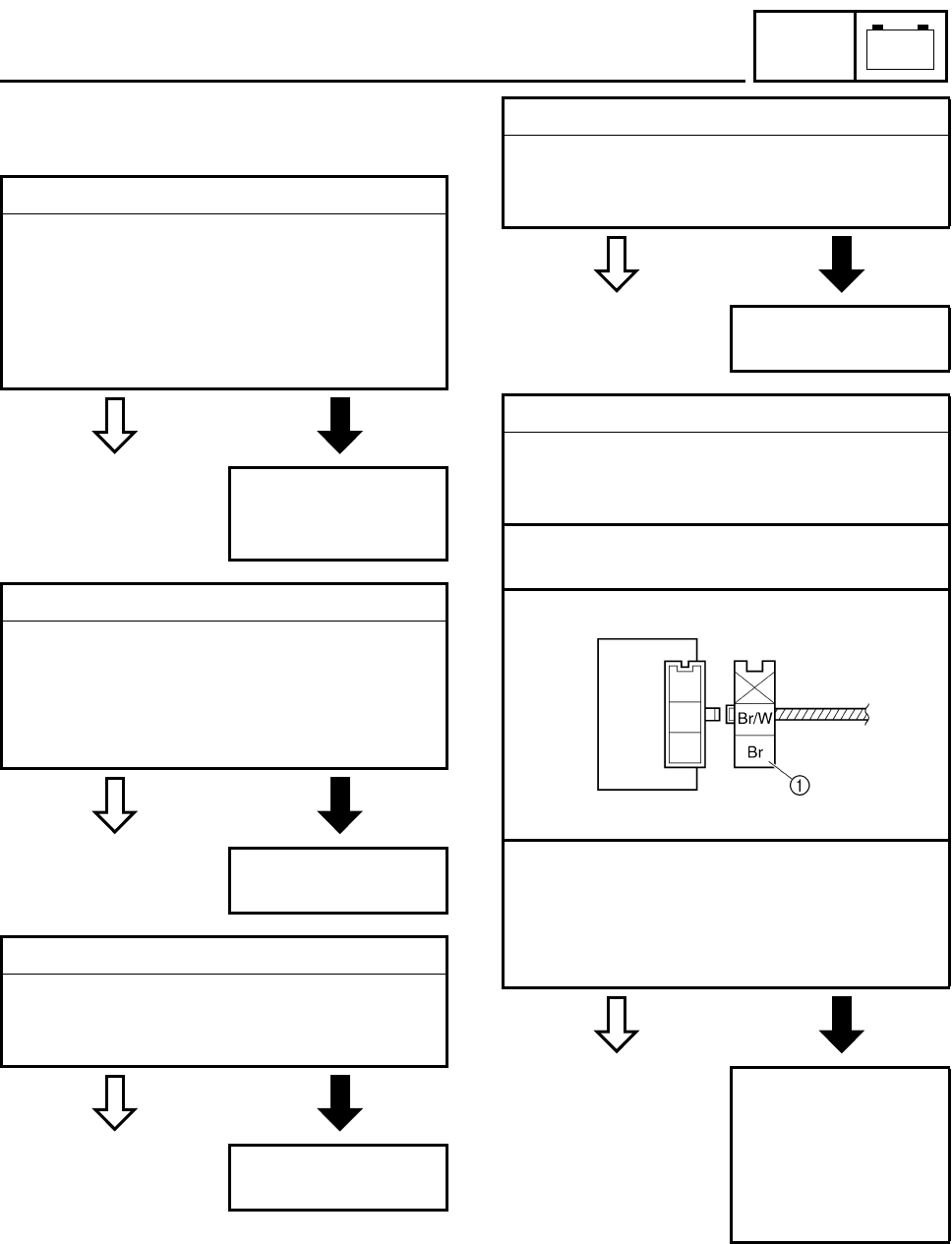
5. Voltage
• Connect the pocket tester (DC 20 V) to the
turn signal/hazard relay coupler (wire har-
ness end) as shown.
Positive tester probe
→
brown
1
Negative tester probe
→
ground
• Set the main switch to “ON”.
• Measure the voltage (DC 12 V) of brown
1
at the turn signal/hazard relay coupler
(wire harness end).
• Is the voltage within specification?
The wiring circuit
from the main switch
to the turn signal/
hazard relay coupler
is faulty and must be
repaired.