


4 - 87
CHAS
SWINGARM AND DRIVE CHAIN
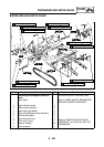
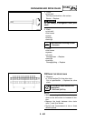
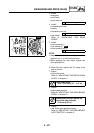
3. Install:
• swingarm
• pivot shaft
• pivot shaft nut
4. Install:
• connecting arm bolt
• washer
• connecting arm nut
• rear wheel
Refer to “INSTALLING THE REAR
WHEEL”.
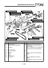
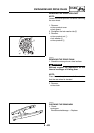
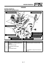
5. Install:
• drive sprocket 1
• lock washer 2
• drive sprocket nut 3
NOTE:
• Install the drive sprocket 1 and drive
sprocket nut 3 in the direction shown.
• While applying the rear brake, tighten the
drive sprocket nut.
6. Bend the lock washer tab a along a flat
side of the nut.
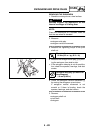
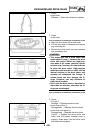
7. Adjust:
• drive chain slack
Refer to “ADJUSTING THE DRIVE CHAIN
SLACK” in chapter 3.
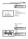
8. Adjust:
• brake pedal position
Refer to “ADJUSTING THE REAR BRAKE
PEDAL” in chapter 3.
9. Adjust:
• rear brake light operation timing
Refer to “ADJUSTING THE REAR BRAKE
LIGHT SWITCH” in chapter 3.
Drive chain slack
40.0 ~ 55.0 mm (1.57 ~ 2.17 in)
Brake pedal position (below the
top of the rider footrest)
12.0 mm (0.47 in)
T
R
.
.
92 Nm (9.2 m · kg, 66 ft · lb)
T
R
.
.
59 Nm (5.9 m · kg, 43 ft · lb)
1
2
3
3
1
a
New
New
T
R
.
.
120 Nm (12.0 m · kg, 85 ft · lb)