


8 - 20
– +
ELEC
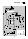
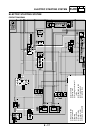
ELECTRIC STARTING SYSTEM
EAS00759
YES
NO
EAS00760
YES
NO
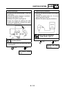
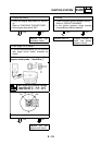
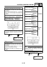
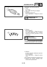
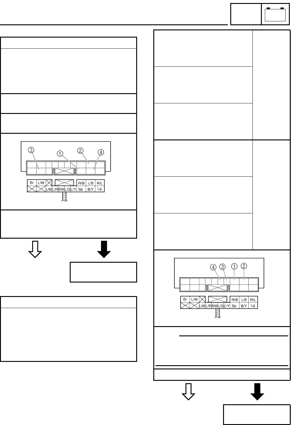
4. Relay unit (starting circuit cut-off relay)
• Disconnect the relay unit from the wire
harness.
• Connect the pocket tester (
Ω
×
1) and bat-
tery (12 V) to the relay unit terminals as
shown.
Positive battery terminal
→
red/black
1
Negative battery terminal
→
black/yellow
2
Positive tester probe
→
blue/white
3
Negative tester probe
→
blue/black
4
• Does the starting circuit cut-off relay have
continuity between blue/white and blue/
black?
Replace the relay
unit.
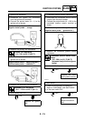
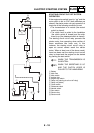
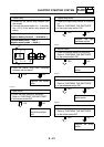
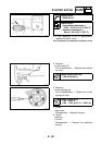
5. Relay unit (diode)
• Disconnect the relay unit from the wire
harness.
• Connect the pocket tester (
Ω
×
1) to the
relay unit terminals as shown.
• Measure the diode for continuity as fol-
lows.
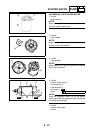
Positive tester probe
→
sky blue
1
Negative tester probe
→
black/yellow
2
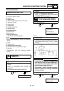
Continuity
Positive tester probe
→
sky blue
1
Negative tester probe
→
blue/yellow
3
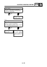
Positive tester probe
→
blue/green
4
Negative tester probe
→
blue/yellow
3
Positive tester probe
→
black/yellow
2
Negative tester probe
→
sky blue
1
No conti-
nuity
Positive tester probe
→
blue/yellow
3
Negative tester probe
→
sky blue
1
Positive tester probe
→
blue/yellow
3
Negative tester probe
→
blue/green
4
NOTE:
_
When you switch the tester’s positive and
negative probes, the readings in the above
chart will be reversed.
• Are the testing readings correct?
Replace the relay
unit.