


7 - 11
FI
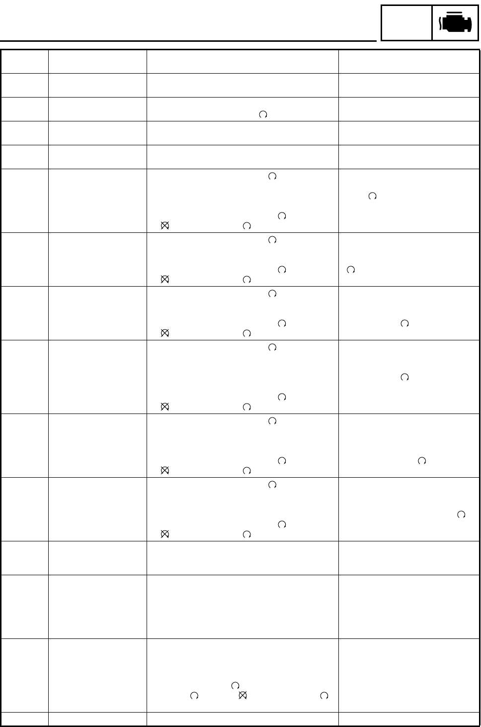
FUEL INJECTION SYSTEM
08
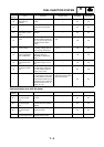
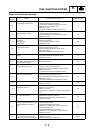
Lean angle cut-off switch Displays the lean angle cut-off switch values. Upright: 0.4 ~ 1.4 V
Overturned: 3.7 ~ 4.4 V
09
Fuel system voltage (bat-
tery voltage)
Displays the fuel system voltage (battery voltage).
Set the engine stop switch to “”.
Approximately 12.0 V
20
Sidestand switch Displays that the switch is on or off. (When the gear
is in a position other than neutral.)
Stand retracted: On
Stand extended: Off
21
Neutral switch Displays that the switch is on or off. Neutral: On
In gear: Off
30
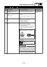
Ignition coil The engine stop switch is set to “”, the ignition
coil operates 5 times every second and the engine
trouble warning light comes on.
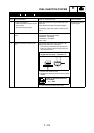
• Connect an ignition checker to the spark plug cap.
• If the engine stop switch is set to “”, set it to
“”, and then set it to “” again.
Check that sparks are generated 5
times with the engine stop switch is
set to “”.
36
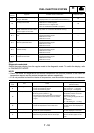
Fuel injector The engine stop switch is set to ““, the fuel injec-
tor operates 5 times every second and the engine
trouble warning light comes on.
• If the engine stop switch is set to “”, set it to
“”, and then set it to “” again.
Check that the operating sound of the
fuel injector is generated 5 times
when the engine stop switch is set to
“”.
48
Air induction system The engine stop switch is set to “”, the air induc-
tion system solenoid operates 5 times every second
and the engine trouble warning light comes on.
• If the engine stop switch is set to “”, set it to
“”, and then set it to “” again.
Check that the operating sound of the
air induction system solenoid is gen-
erated 5 times when the engine stop
switch is set to “”.
50
Fuel injection system
relay
The engine stop switch is set to “”, the fuel injec-
tion system relay operates 5 times every second
and the engine trouble warning light comes on (on
when relay is operating, off when relay is not operat-
ing).
• If the engine stop switch is set to “”, set it to
“”, and then set it to “” again.
Check that the operating sound of the
fuel injection system relay is gener-
ated 5 times when the engine stop
switch is set to “”.
51
Radiator fan motor relay The engine stop switch is set to ““, the radiator
fan motor relay operates 5 times, 5 seconds each
time (2 seconds on, 3 seconds off), and the engine
trouble warning light comes on.
• If the engine stop switch is set to “”, set it to
“”, and then set it to “” again.
Check that the operating sound of the
radiator fan motor relay is generated
and that the radiator fan motor is
operated 5 times when the engine
stop switch is set to “”.
52
Headlight relay 1 The engine stop switch is set to “”, the headlight
relay operates 5 times, 5 seconds each time (2 sec-
onds on, 3 seconds off), and the engine trouble
warning light comes on.
• If the engine stop switch is set to “”, set it to
“”, and then set it to “” again.
Check that the operating sound of the
headlight relay is generated and that
the headlight comes on 5 times when
the engine stop switch is set to “”.
60
E2PROM fault code dis-
play
• Transmits the abnormal portion of the data in the
E2PROM that has been detected as fault code 44.
01
“00” is displayed when there is no
malfunction.
61
Malfunction history code
display
• Displays the codes of the history of the self-diag-
nosis malfunctions (i.e., a code of a malfunction
that occurred once and which has been corrected).
• If multiple malfunctions have been detected, differ-
ent codes are displayed at 2-second intervals, and
this process is repeated.
12 ~ 61
“00” is displayed when there is no
malfunction.
62
Malfunction history code
erasure
• Displays the total number of codes that are being
detected through self diagnosis and the fault codes
in the past history.
• Erases only the history codes when the engine
stop switch is set to “”. If the engine stop switch
is set to “”, set it to “”, and then set it to “”
again.
00 ~ 17
“00” is displayed when there is no
malfunction.
70 Control number • Displays the program control number. 00 ~ 255
Diagnostic
code
Item Action
Data displayed on meter
(reference value)