22 997-01530-01, Rev. C-25, Jan 2008
SSSSSSSSSSSS SSSS SSSSSS SSSSSSS S SSS SSSSSSS
1
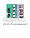
generate 10 MPPS and the procedure would be complete. The same method can be used to configure
any of the outputs.
Note: PPO and Alarm are only available if those options have been purchased and are enabled using
F126 – Options Key Entry (page 108).
Note: F90 – Code Output Configuration does not control the IRIG signals on the Expansion Module.
Verifying Antenna Installation
After completing the above steps, use the keypad to verify the following:
•In F119 – GPS Receiver Configuration
(page 104), after approximately 20 minutes of operation,
check that GPS STATUS is LOCKED and GPS ANTENNA is OK.
•In F73 – Alarm Control / Status
(page 64), check that the GPS PRI is OK and is ALARM
ENABLED (the same for GPS SEC, if two GPS receivers are present). Clear any alarm latches if
present.
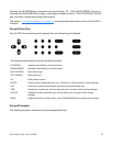
• Press the STATUS key. “LOCKED GPS PRI” should appear on the front panel display without
an asterisk. If an asterisk appears, it means that a reference source is not available.
To troubleshoot a problematic Antenna installation, recheck the physical location of the antenna, the
cabling, and the configuration settings described in this manual.
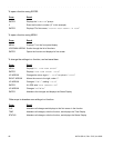
Switch Position Signal Type
0Off
1 10 MPPS
2 5 MPPS
3 1 MPPS
4 100 kPPS
5 10 kPPS
6 1 kPPS
7 1 PPS
8 Code DC (IRIG-B DC Time Code)
9 PPO
AAlarm
B-F Not Used


