


16 997-01530-01, Rev. C-25, Jan 2008
SSSSSSSSSSSS SSSS SSSSSS SSSSSSS S SSS SSSSSSS
1
– J2 Output (Rate, PPO)” on page 96, “F113 – J3 Input (Freq Meas)” on page 100.
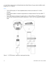
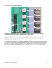
Figure 3: Connectors: ANTENNA, SERIAL I/O, J1, J2, J3, NET, 1 PPS, CODE, ALARM
Connecting the Power Supply
Warning: Ensure that a disconnect device, such as a switch, with the appropriate voltage/
current rating is provided when operating/installing the XL-GPS.
Connect the Power Supply it to a power source. The green STATUS light indicates that the XL-GPS is
receiving power.
Notes for optional DC power supplies:
• Use a 15 amp circuit breaker in series with the DC power source; don’t connect directly to a DC
power source without the breaker.
• 14 gage wire is the minimum recommended for DC power source hookup.
• DC Power Supply Only to be used in a restricted access area.
• The screw torque range on the Power Terminal Block is 5 to 8 inch pounds.
• When connecting to a DC power source, first connect the positive power cable to “+” on the
power supply, then connect the negative power supply cable to “−”.
Upon receiving power, the XL-GPS goes through its startup sequence; displaying “Booting”, Loading”,
and “Starting”. After approximately 40 seconds, the XL-GPS displays the clock status, and user
interfaces (front panel/command line) become available.
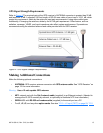
Configuring the Network Port
The following additional steps are required to make the XL-GPS operational on a network. Make the XL-
GPS operational on a network if you plan on:
• Managing the XL-GPS remotely over the network
• Distributing timing information from the XL-GPS over the network
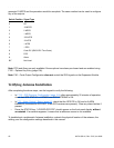
Press Result
ENTER Displays “FUNCTION”
100 Enters 100 as the function number