


5-12 Raychart 320 Chartplotter
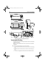
Antenna Connector
The ANTENNA connector provides power and RF connection to the
associated GPS Antenna.
CAUTION:
Do not connect/disconnect the GPS Antenna from the display unit
whilst power is applied. Such action could cause irreparable
damage.
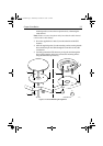
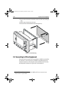
➤ Connect the antenna using the attached cable, as follows:
1. If not already installed, mount the GPS Antenna as described in
Section 5.3.
2. Feed the cable through to the rear of the Chartplotter.
3. Coil up any unused cable in an appropriate safe space out of view. Do
not bend the cable tighter than 4in (100mm) radius.
4. Screw the cable connector fully into its mating connector on the
Chartplotter.
5. Ensure that the protective boot covers the connector.
Note: If the supplied cable is too short, use an extension cable (Part#
E36011), or consult your Raymarine dealer.
It is recommended that only a single extension cable is used as each extra
connector will reduce signal levels.
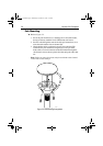
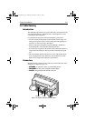
PWR/NMEA Connector
CAUTION:
If you do not have a breaker in your power circuit, you must fit an
in-line 1A quick-blow fuse to the positive (red) lead of the power
cable.
This unit is not intended for use on positive ground vessels.
The Chartplotter is intended for use on vessels’ DC power systems
operating in the range 12VDC to 24VDC (9.0VDC to 32.0VDC
maximum range). A 5ft (1.5m) power cable is supplied.
The power connections should be made at a DC power distribution panel
through an isolator switch, a 1A circuit breaker or a 1A quick blow fuse.
Check that all connections are clean and tight.
The DC power system should be either:
• Negative ground, with the negative battery terminal connected to the
vessel’s ground.
• Floating, with neither battery terminal connected to the vessel’s
ground.
81167_3.BOOK Page 12 Wednesday, November 21, 2001 2:12 PM