


F8QT ENGINE -
Fuel Injection Pump
11A-19-6
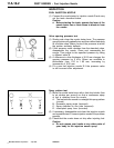
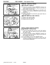
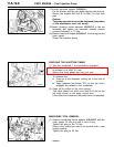
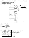
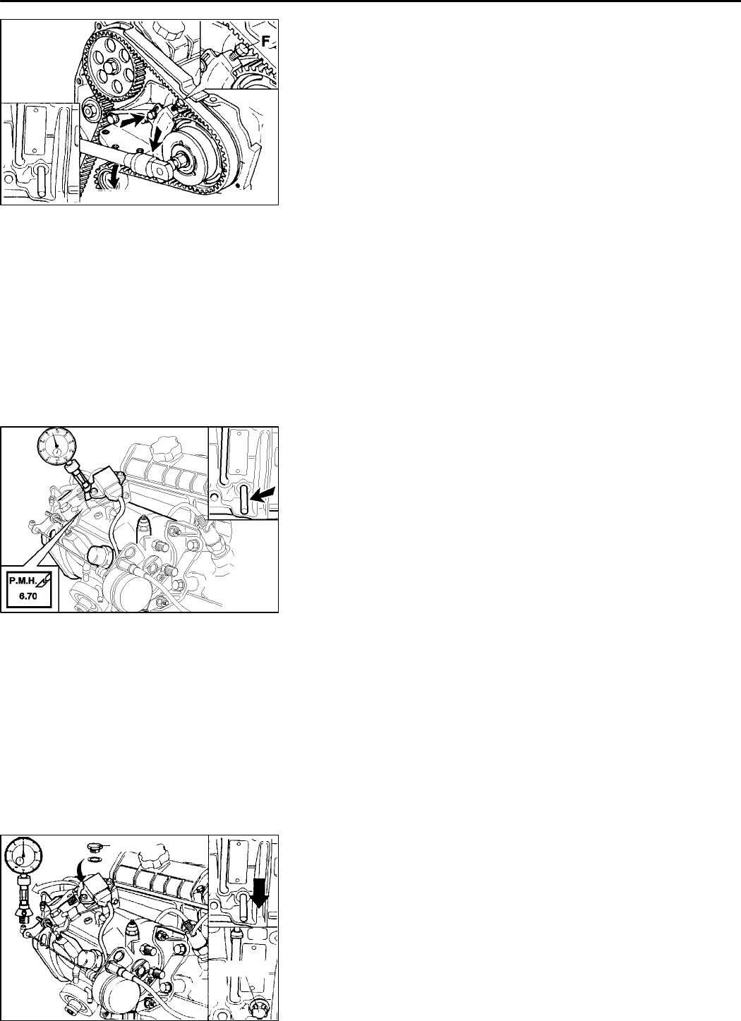
(11)Locate sprocket stopper MB996043.
Fix the bracket with the two bolts supplied with the set.
Secure the bracket with bolt
F
so that it is free from
play.
Caution
The pump sprocket must not be displaced (the pointer
of the micrometer must not move).
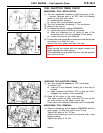
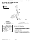
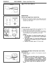
(12)Insert Hexagon socket spanner MB996036 in the nut
assembly and tighten the assembly steadily (turning
counter-clockwise) to 70 Nm.
(13) Remove sprocket stopper MB996043, the locking pin and
clock gauge.
Check the injection timing.
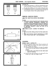
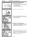
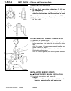
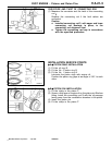
CHECKING THE INJECTION TIMING
(1) Turn the crankshaft 1 3/4 revolutions clockwise.
(2) Position the clock gauge and make sure that the plunger
is pressed in at least 0.2 mm.
Secure the clock gauge and set it at zero.
(3) Turn the crankshaft
exactly
to TDC (clockwise).
To achieve this:
D Insert an 8 mm diameter locking pin in the hole of
torxbolt.
D Apply pressure just before TDC on this pin until it
engages the recess in the crankshaft.
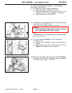
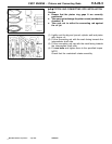
(4) Read off the value on the clock gauge.
This value should not differ more than 0.02 mm as the
set value shown on th e pump control arm.
If the value is not obtained, the pump has to be adjusted.
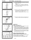
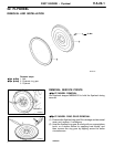
MEASURING TOOL REMOVAL
(1) Remove measuring device adaptor MB996030 with the
clock gauge. Fit the plug with a new O-ring.
Tighten the plug to the 10 Nm.
Remove the locking pin and fit the torxbolt with a new
sealing washer.
Tighten the plug to 20 Nm.
PWEE9602
E
July 1996Mitsubishi Motors Corporation
REN0160
70 Nm
REN0161
REN0151
10 Nm
20 Nm