


F8QT ENGINE -
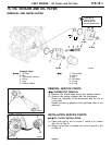
Camshaft, Intake and Exhaust Valves
11A-13-7
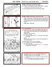
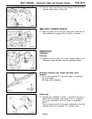
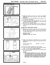
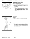
(3) Heat the cylinder head to about +100_C.
(4) Install the intake valve seat on valve seat installer
MB996022 and exhaust valve seat on valve seat installer
MB996023.
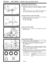
(5) Immerse the valve seats
24, 25
in liquid nitrogen so as
to cool them sufficiently.
(6) Pressing the valve seats
24, 25
with the valve seat
installers MB996022 and MB996023 in the bores until
they abut in the cylinder head.
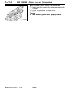
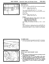
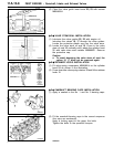
(7) After the valve seats
24, 25
have been installed, the
valve seats and the valves
16, 17
must be matched by
lapping.
"
C
A
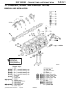
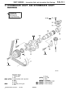
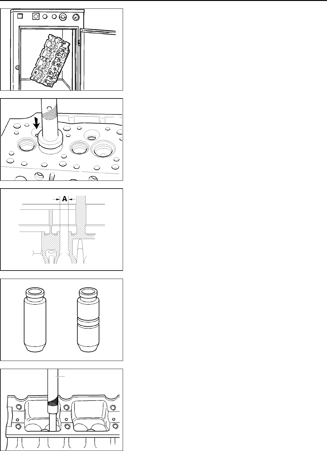
VALVE GUIDE INSTALLATION
(1) Measure th e diameter of the bores for the valve guides
22, 23
in the cylinder head
31
. If a measured value does
not come within the specified tolerance range, select the
oversize valve guide.
Standard value:
Diameter of bore (A): 13 mm
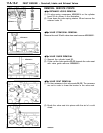
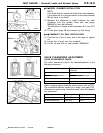
(2) Ream valve guide bore (dimension A) to the outside
diameter of the selected oversize valve guides withreamer
MB996016.
Oversize valve guide diameter = 13.3 mm
(two grooves)
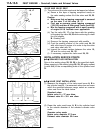
(3) Place the cylinder head
31
on a flat surface.
(4) Locate the valve guides
22, 23
, with the taper pointing
down, on valve guide installer MB996029.
(5) Press in the valve guides
22, 23
until the installer abuts
the cylinder head
31
.
Caution
D
The pressure exerted on the valve guide must
be at least 9,000 N. If the pressure is lower, the
valve guide must be removed. Ream the valve
guide bore inthe cylinderhead to the nextoversize
and press in the corresponding valve guide.
PWEE9602
E
July 1996Mitsubishi Motors Corporation
REN0067
REN0068
3-4 sec.
REN0069
REN0070
REN0071
MB996029
9,000 N