


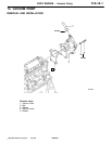
F8QT ENGINE -
Camshaft, Intake and Exhaust Valves
11A-13-6
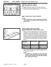
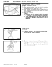
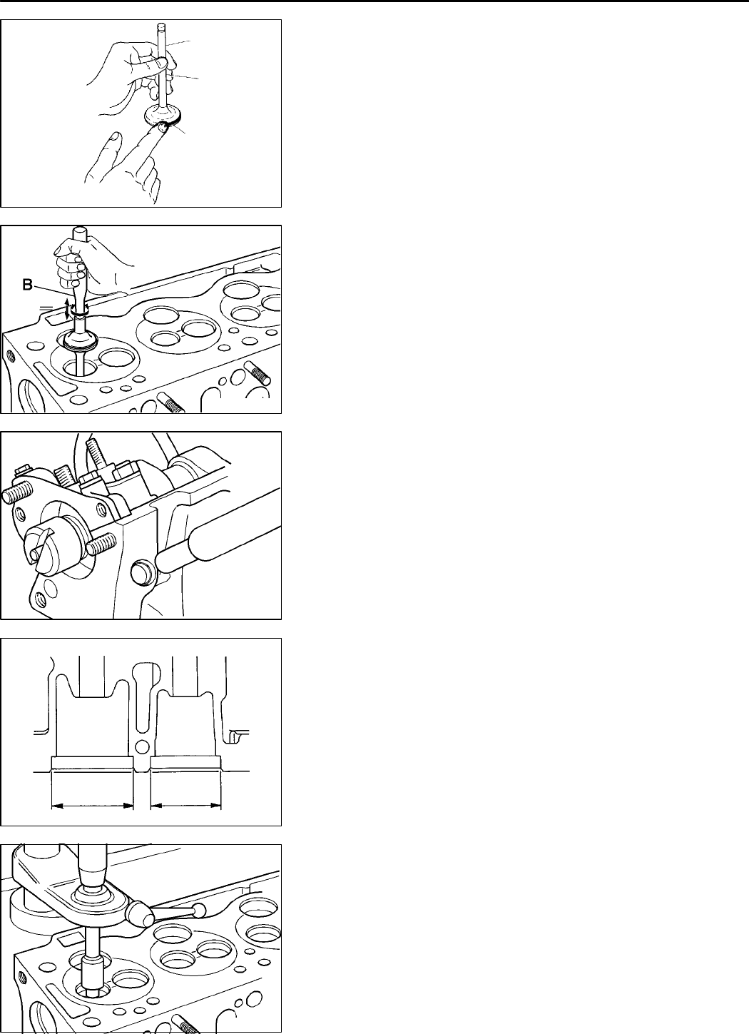
VALVE AND VALVE SEAT
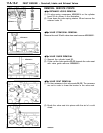
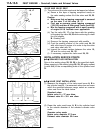
(1) The valve and the valve seat must be lapped as follows:
(a) Smear a thi n l ayer of lapping compound evenl y on
the valve seating surfac e
A
of the valv e seat
24, 25
.
Caution
D
Make sure that no lapping compound is smeared
on the stem C of the valve 16, 17.
D
First use an average grade lapping compound
(120-150) and then a finer grade (more than 200).
D
Mix the lapping compound with a small quantity
of engine oil to facilitate even application.
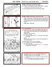
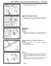
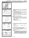
(b) Tap the valve
16, 17
a few times with the grinding
tool against the valve
24, 25
while continuing to rotate
the tool slightly.
B
: Grinding tool
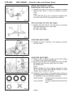
(c) Remove the lapping compound with paraffin
(d) Coat the seating surface of the valve seat
24, 25
with a thin layer of engine oil in order to lap the valve
and valve seat with oil.
(e) Inspect the contact surface between the valve
15,
16
and the valve seat
24, 25
.
(f) If necessary, replace the valve seat
24, 25
.
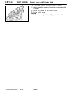
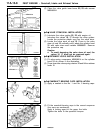
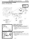
INSTALLATION SERVICE POINTS
"
A
A
SEALING PLUG INSTALLATION
Drive in the sealing plugs
28, 29, 30
to the specified depth.
When pressing in the sealing plugs
28, 29, 30
apply sealant
(Loctite 648) to the corresponding holes in the cylinder head
31
.
"
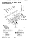
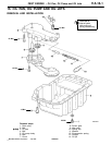
B
A
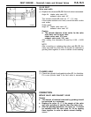
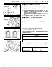
VALVE SEAT INSTALLATION
(1) Measure the diameter of the valve seat bores
A, B
in
the cylinder head
31
. If a measured value does not come
within the specified tolerance range, select an oversize
valve seat from the table below.
Standard value:
Intake valve A = 37 mm diam.
Exhaust valve B = 32.1 mm diam.
(2) Ream the valve seat bores
A, B
in the cylinder head
to the outside diameter of the selected oversize valve
seats.
Oversize valve seats:
Intake valve diameter 37.3 mm
Exhaust valve diameter 32.4 mm
PWEE9602
E
July 1996Mitsubishi Motors Corporation
4ME0131
16, 17
A
C
REN0063
REN0064
REN0065
AB
REN0066