


14
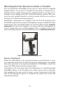
If possible, keep the power cable away from other boat wiring, espe-
cially the engine's wires. This will provide the best isolation from elec-
trical noise. If the cable is not long enough, splice #18 gauge wire onto
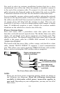
it. The display power cable has three wires, white, red and black. Red is
the positive (+) lead, black is negative (–) or ground. The white wire is
unused by your unit and should be capped. Make sure to attach the in-
line fuse holder to the red lead as close to the power source as possible.
For example, if you have to extend the power cable to the power bus or
battery, attach one end of the fuse holder directly to the power bus or
battery. This will protect both the unit and the power cable in the event
of a short. This unit has reverse polarity protection. No damage will
occur if the power wires are reversed. However, the unit will not work
until the wires are attached correctly.
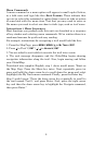
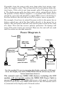
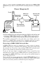
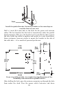
Power Diagram A
Use this method if you are powering the display unit and a GPS mod-
ule or the display unit and a NMEA 2000 network. (Fuses may be dif-
ferent from those shown.).
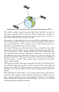
The network and any NMEA 2000 devices, including the GPS
module, will not operate
unless the NMEA 2000 Power Cable is
connected to power. The NMEA 2000 power cable must be connected
to power even if your only NMEA 2000 device is the GPS module and it
is connected to the display unit's Network socket.
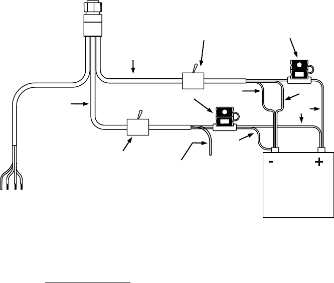
Shield
Mandatory
network
power-off
switch
Black
Black
Red
Recommended
display unit
p
ower-off switch
To unit
12 volt DC
power source
Data Cable
NMEA 2000
Power Cable
3-amp fuse
3-amp fuse
Display Unit
Power Cable
White
(unused)