


12
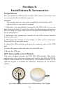
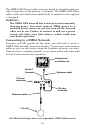
You need to select an antenna installation location that has a clear,
unobstructed view of the sky. After the module is installed, connect it
to the end of the extension cable. To connect it to the unit, insert the
cable's plug into the Network socket on the back of the unit or a double
T connector attached to the unit. See the module's instruction sheet.
In an automobile, you may achieve good results by placing the external
antenna on the top of the dash, at the base of the windshield. A piece of
the rubber non-skid shelf liner material available in recreational vehi-
cle supply stores will help hold the antenna in place. This may not
work well if you have a cab-over design pickup truck camper or motor
home. If dashboard reception is poor, relocate the antenna module
elsewhere on the vehicle for a clearer view of the sky.
Power Connections
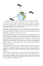
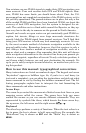
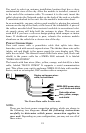
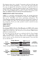
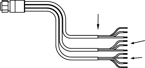
Your unit comes with a power/data cable that splits into three
branches, each with several exposed wires. The thicker three-wire cable
(white, red and black) is the power supply for your display unit. This
cable has no label. The thinner branch with three wires (red, black and
shield) is the power cable for a NMEA 2000 network. It is labeled
"NMEA 2000 POWER."
The branch with four wires (blue, yellow, orange, and shield) is a data
cable, labeled "RS-232 COMM." It supports a serial communication
port. This allows your unit to exchange NMEA 0183 data with another
device, such as an autopilot, DSC marine radio or computer.
The Power/Data cable for this unit.
NOTE:
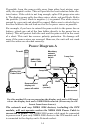
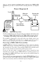
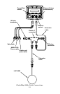
There are two basic power connection options, which are shown in
the following two diagrams. Read the following instructions
carefully to determine which power connection applies to
your unit. Depending on your configuration, you may not use all of
these wires.
To unit
Display unit power wires:
white, red and black
NMEA 2000 power wires:
red, black and shield
Data cable wires:
blue, yellow, orange,
and shield