


Garmin G1000 Cockpit Reference Guide for the DA40/40F
SECTION 6 – AUTOMATIC
FLIGHT CONTROL
6-1
SECTION 6: AUTOMATIC FLIGHT
CONTROL
The GFC 700 AFCS is optional on the DA40 and
DA40F. In aircraft without the GFC 700 option, refer
to the operating instructions for the installed autopilot
system for details.
In addition to the AFCS (Automatic Flight Control
System) keys on the MFD, as discussed in the System
Overview section, the following buttons and switches
used by the AFCS are located in the cockpit separately
from the PFD and MFD.
• AP DISC (Autopilot Disconnect) Button —
Located on the left and right control sticks, pressing
this button disengages the autopilot. Pressing it also
acknowledges an autopilot disconnect.
• CWS (Control Wheel Steering) Button —
Located on the left and right control sticks, pressing
and holding the CWS button disengages the control
surface servos without disengaging the autopilot. If
the flight director has not been activated, pressing
the CWS button will activate the flight director in
the default pitch and roll hold modes.
• GA (Go Around) Button — Located on the throttle
lever, the GA button disengages the autopilot and
selects the Go Around (wings level) mode.
• AP TRIM (Autopilot Trim) Switch — Located on
the left control stick, this switch is used to operate
manual electric pitch trim. Moving both switches
forward simultaneously trims the aircraft nose down.
Moving both switches aft simultaneously trims the
aircraft nose up. The left switch is the ARM contact
and the right switch controls the up/down trim.
Pressing the ARM switch disengages the autopilot, if
currently engaged. If one side of the switch is active
for more than three seconds without the other side
also being active, ‘PTRM’ is displayed in the
AFCS
System Status Box on the PFD. Pressing the ARM
switch also acknowledges an autopilot disconnect.
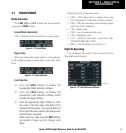
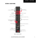
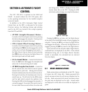
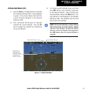
Figure 6-1 AFCS Keys
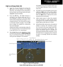
Pressing the FD Key activates only the flight director
in the default Pitch Hold/Roll modes without engaging the
autopilot. Pressing the AP Key activates the flight director
and engages the autopilot. When only the flight director is
engaged, pressing the FD Key removes the flight director.
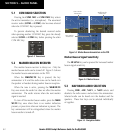
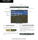
Upon activation of the autopilot and/or flight director,
command bars are displayed on the PFD. If the attitude
information being sent to the flight director becomes
invalid or unavailable, the command bars are removed
from the display.
Figure 6-2 Command Bars
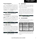
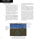
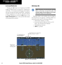
6.1 MODE ANNUNCIATIONS
Mode annunciations are displayed on the PFD. Figure
6-3 shows the AFCS Status Box. Modes associated with
aircraft movement about the roll axis are displayed on the
left side. Modes associated with aircraft movement about
the pitch axis are displayed on the right. Armed modes
are displayed in white and active modes are displayed in
green.