


Garmin G1000 Cockpit Reference Guide for the DA40/40F
SECTION 3 – ENGINE
INDICATION SYSTEM (EIS)
3-1
SECTION 3: ENGINE INDICATION
SYSTEM (EIS)
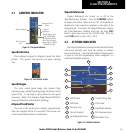
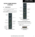
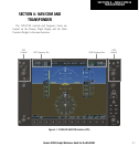
3.1 ENGINE DISPLAY
In all cases green indicates normal operation, yellow
indicates caution, and red indicates warning.
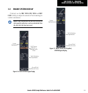
Pressing the
ENGINE Softkey makes available the
LEAN and SYSTEM Softkeys which in turn provide access
to the Lean Display and the System Display, respectively.
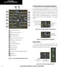
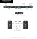
Figure 3-1 DA40 Default Engine Display
Manifold
Pressure
Gauge
RPM Gauge
Ammeter
Cylinder Head
Temperature
Indicator
Oil Pressure
Indicator
Voltmeter
Fuel Quantity
Indicator (scale
is 0 - 25 with
extended range
fuel tanks)
Oil Temperature
Indicator
Fuel Flow
Indicator
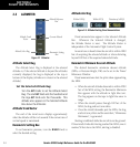
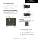
Figure 3-2 DA40F (Fixed Pitch Propeller)
Default Engine Display
RPM Gauge
Ammeter
Cylinder Head
Temperature
Indicator
Oil Pressure
Indicator
Voltmeter
Fuel Quantity
Indicator
Oil Temperature
Indicator
Fuel Flow
Indicator
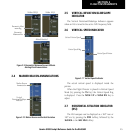
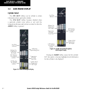
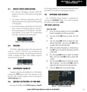
Fuel Pressure Indicator (Option, DA40 only)
Located between the Fuel Flow and CHT Indicators
and shows the fuel pressure in pounds per square inch.
• Green – Normal
• Red – Warning (minimum and maximum)
Figure 3-3 Fuel Pressure Indicator
(Showing Warning)